Method for manfacturing an acoustic matching member

a technology of acoustic matching and acoustic wave, which is applied in the field of acoustic matching members, can solve the problems of difficult measurement of propagation time, weak strength of acoustic waves that have passed through the area, and not so many applications of such a configuration

Inactive Publication Date: 2008-06-24
PANASONIC CORP
View PDF28 Cites 9 Cited by
  • Summary
  • Abstract
  • Description
  • Claims
  • Application Information

AI Technical Summary

Benefits of technology

[0026]Therefore, with the foregoing in mind, it is an object of the present invention to provide an acoustic matching member in which delamination hardly occurs so as to have less malfunction, and an ultrasonic transducer, an ultrasonic flowmeter using the same and methods for manufacturing them.

Problems solved by technology

In such an ultrasonic flowmeter, the continuous application of an AC voltage results in the continuous emission of ultrasonic waves from the ultrasonic transducer, which makes it difficult to measure the propagation time.
On a boundary surface between the substances with the thus different acoustic impedances, reflection occurs in the propagation of acoustic waves, so that the strength of the acoustic waves that have passed through there becomes weak.
However, there are not so many applications of such a configuration.
As a result, (1) the bonding face between the layers is weak physically, and therefore delamination becomes likely to occur during transmission and reception of ultrasonic waves due to the vibration, which causes malfunctions of the acoustic matching member and of an ultrasonic transducer and an ultrasonic flowmeter using the same.
Therefore, it becomes difficult to design the acoustic matching layer optimally.
That is to say, the physical properties (density and velocity of sound) of the bonding material as an intermediate layer and the shape after bonding (thickness of the intermediate layer) cannot be ignored, so that the design becomes difficult.
Even when the design can be done, the problems of limited options for bonding materials and complicated control of the thickness of the intermediate layer cannot be avoided.
(3) The complicated manufacturing method in which different members are prepared individually and are attached results in an increase in the manufacturing cost of the ultrasonic transducer and of an ultrasonic flowmeter.
Especially, when a porous member as the low density member is selected for the attached acoustic matching member on the above-stated grounds of the principles, the bonded surface is not a flat face but many voids are present, which means that the practically effective bonding area is significantly small.
Since the adhesion properties decrease with decreases in effective bonding area, the above problem (1) becomes more pronounced.
Also in the case where a liquid state material is applied to a porous member as the first layer, followed by drying and curing so as to form the second layer, the generation of an intermediate layer formed by the porous member impregnated with the liquid state material cannot be avoided, and therefore the similar problems would occur.

Method used


Image

  • Method for manfacturing an acoustic matching member
  • Method for manfacturing an acoustic matching member
  • Method for manfacturing an acoustic matching member

Examples


embodiment 1

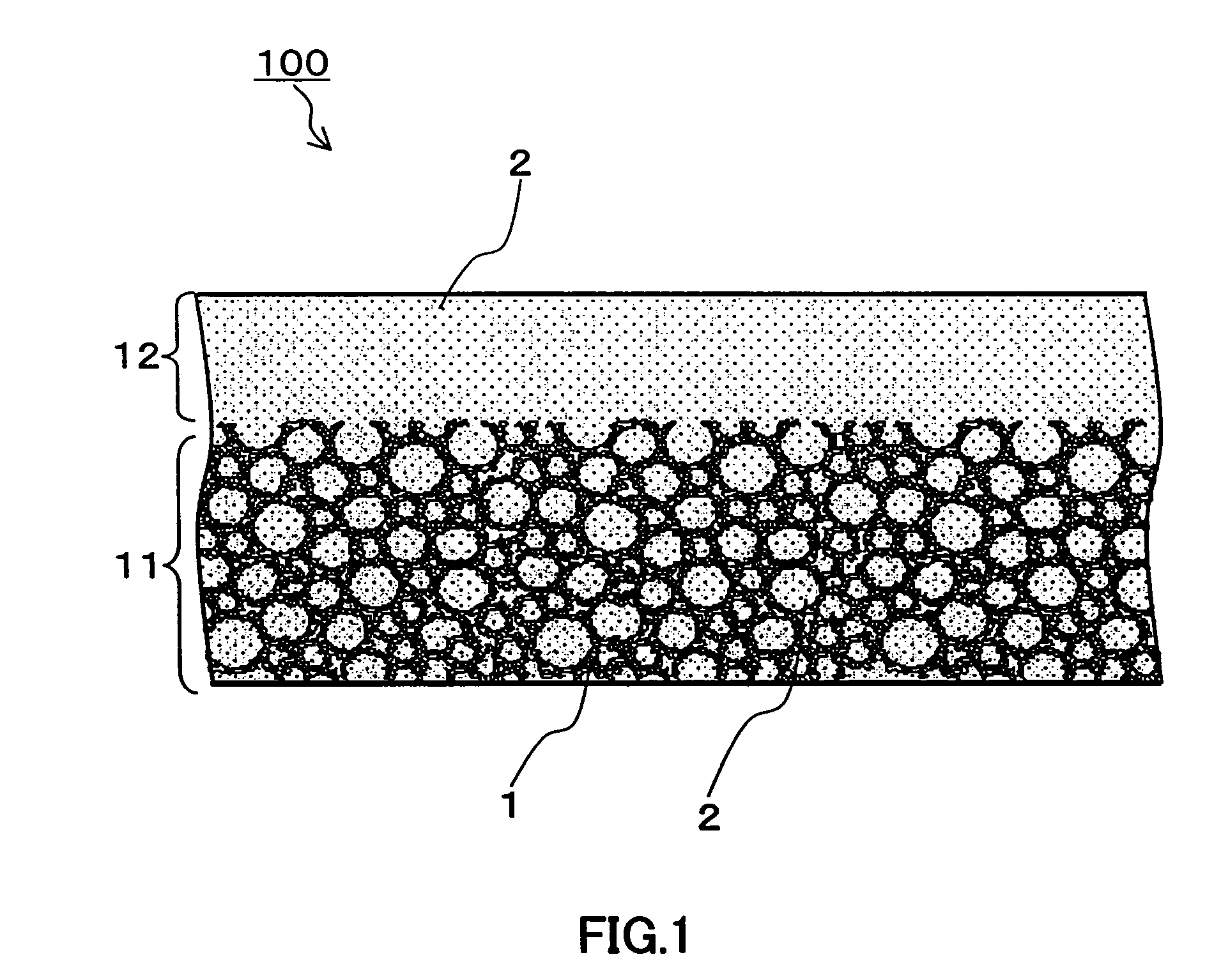
[0067]Embodiment 1 of the present invention is an acoustic matching member 100 made up of a first layer 11 and a second layer 12 as shown in FIG. 1. The first layer 11 is a composite material made up of a porous member 1 and a filling material 2, where a void portion of the porous member 1 is impregnated with the filling material, and the filling material is cured therein and supported by the void portion. The second layer 12 is made of the same material as the filling material in the first layer. There exists at least one continuously integrated portion between the filling material in the first layer 11 and the material of the second layer 12. That is to say, the filling material 2 making up the second layer 12 and the filling material 2 in the first layer 11 are formed by solidifying simultaneously, so that they have physical continuity.

[0068]The filling material 2 making up the second layer 12 penetrates through the interior of the void portions of the porous member in the first ...

embodiment 2

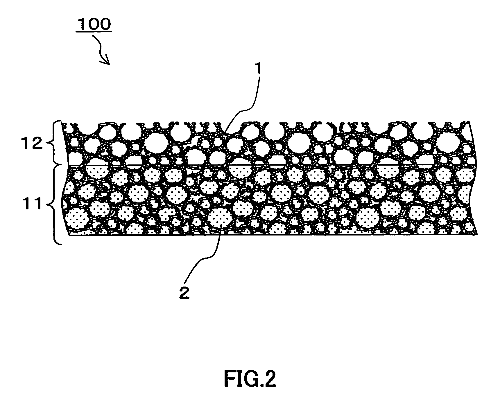
[0071]Embodiment 2 of the present invention is an acoustic matching member 100 made up of two layers including a first layer 11 and a second layer 12 as shown in FIG. 2. The first layer 11 is a composite material made up of a porous member 1 and a filling material 2, where a void portion of the porous member 1 is impregnated with the filling material, and the filling material is cured therein and supported by the void portion. The second layer 12 is made of a portion of the porous member 1 having voids, which makes up the first layer 11. The acoustic matching member according to Embodiment 2 is configured with two layers by filling the lower layer in one porous member 1 with the filling material 2. That is to say, the acoustic matching member has the first layer made of the composite material made up of the skeleton and the void portions of the porous member 1 impregnated with the filling material 2, where the filling material 2 is cured therein, and the second layer made up of only...

embodiment 3

[0084]FIG. 3 is a cross-sectional view showing an ultrasonic transducer according to Embodiment 3 of the present invention. An ultrasonic transducer 200 in FIG. 3 is made up of the acoustic matching member 10 described in the above Embodiment 1 or 2 of the present invention, a piezoelectric member 3 and electrodes 4. The acoustic matching member 10, as described above, has a double layered structure including a first layer 11 and a second layer 12, and the piezoelectric member 3 is disposed on the first layer side of the acoustic matching member. The piezoelectric member 3, which generates ultrasonic vibrations, is made of a piezoelectric ceramic, a piezoelectric single crystal or the like. The piezoelectric member 3 is polarized along the thickness direction and has electrodes 4 on the upper and lower surfaces. The acoustic matching member 10 functions so as to transmit ultrasonic waves to a gas or to receive ultrasonic waves that have propagated through a gas, and plays a role of ...


PUM

PropertyMeasurementUnit
acoustic impedanceaaaaaaaaaa
acoustic impedancesaaaaaaaaaa

Abstract

A method for manufacturing an acoustic matching member, the acoustic matching member being incorporated into an ultrasonic transducer for transmitting and receiving ultrasonic waves, and including: at least two layers including a first layer and a second layer that have different acoustic impedance values from each other. The method for manufacturing including the steps of: filling voids of a porous member with a fluid filling material, and solidifying both the fluid filling material inside the voids and the surplus fluid filling material at the same time. The acoustic matching member does not have independent intermediate layers between the layers, so that delamination hardly occurs and the difficulty in the designing associated with the presence of intermediate layers can be avoided.

Description

BACKGROUND OF THE INVENTION[0001]1. Field of the Invention[0002]The present invention relates to an acoustic matching member used for an acoustic matching layer of an ultrasonic sensor, an ultrasonic transducer for transmitting / receiving ultrasonic waves, a method for manufacturing them, and an ultrasonic flowmeter using them.[0003]2. Related Background Art[0004]In recent years, an ultrasonic flowmeter has been used as a gas meter and the like, where a time for ultrasonic waves to propagate through a propagation path and a velocity of fluid moving therein are measured so as to determine a flow rate of the fluid. FIG. 13 shows the principles of measurement by the ultrasonic flowmeter. As shown in FIG. 13, within a measurement tube including a flow path, fluid flows at a velocity of V in the direction shown by the arrow in the drawing. In a tube wall 103, a pair of ultrasonic transducers 101 and 102 is disposed so as to oppose each other. The ultrasonic transducers 101 and 102 are con...

Claims


Application Information

Patent Timeline
Patent Type & Authority Patents(United States)
IPC IPC(8): H01L41/22H01L41/00G10K11/02
CPCG10K11/02Y10T29/4913Y10T29/49155Y10T29/49007Y10T29/49005Y10T29/49165Y10T29/42
Inventor SHIRAISHI, SEIGOTAKAHARA, NORIHISASUZUKI, MASAAKIHASHIMOTO, KAZUHIKOHASHIDA, TAKASHINAGAHARA, HIDETOMOHASHIMOTO, MASAHIKO
Owner PANASONIC CORP
Why Eureka
Try Eureka