
System for measuring a parameter of an aerated multi-phase mixture flowing in a pipe

a multi-phase mixture and measurement system technology, applied in the direction of instruments, volume metering, specific gravity measurement, etc., can solve the problems of difficult technical challenge of well head monitoring and relatively limited commercial success of products

Active Publication Date: 2008-06-24
EXPRO METERS
View PDF142 Cites 55 Cited by
  • Summary
  • Abstract
  • Description
  • Claims
  • Application Information

AI Technical Summary

Benefits of technology

This system provides accurate and timely monitoring of multi-phase fluid flows, improving the measurement of mass flow rates and densities, thereby optimizing well head production by accounting for the variability of gas and liquid mixtures.

Problems solved by technology

Metering well head production rates is a long standing challenge for the oil and gas industry.
Well head monitoring represents a difficult technical challenge.
The difficulty is due in no small part to the extreme variability of produced fluids which can include various types and mixtures of oil, water, gas, and solid particles.
These products have met relatively limited commercial success due to a combination of performance, accuracy, and cost issues.

Method used


Image

  • System for measuring a parameter of an aerated multi-phase mixture flowing in a pipe
  • System for measuring a parameter of an aerated multi-phase mixture flowing in a pipe
  • System for measuring a parameter of an aerated multi-phase mixture flowing in a pipe

Examples


first embodiment

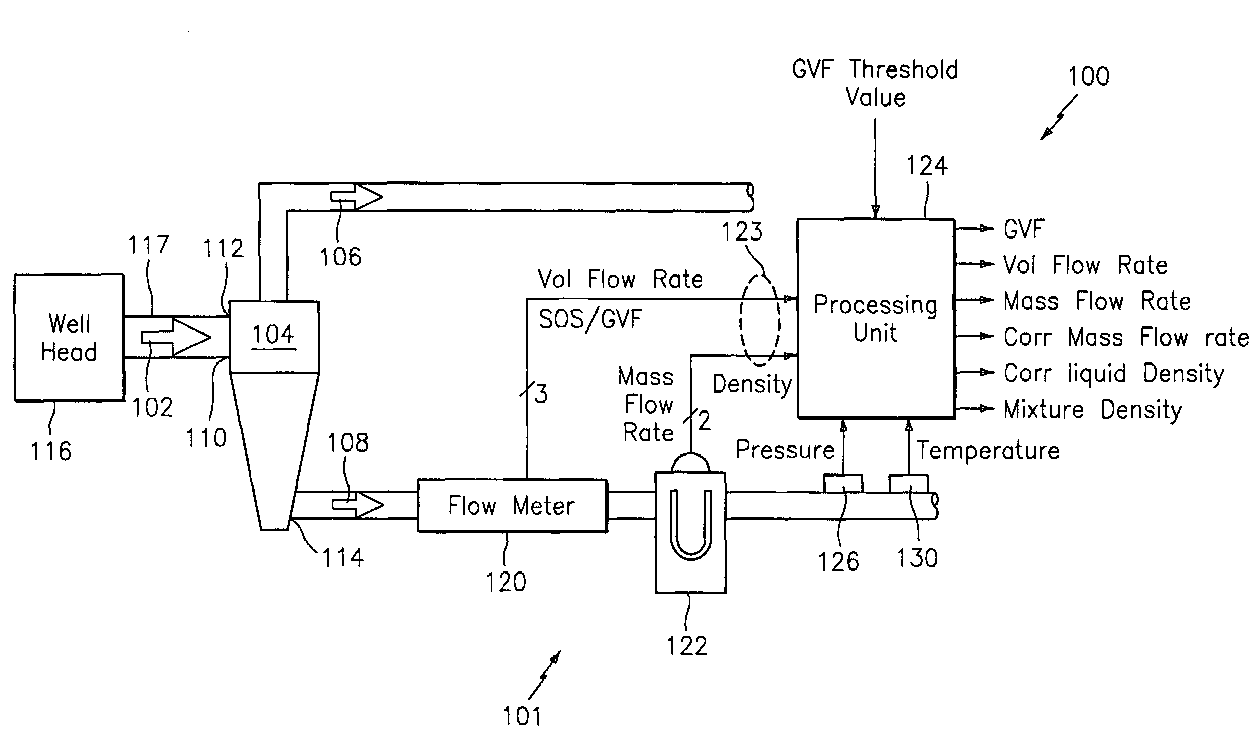
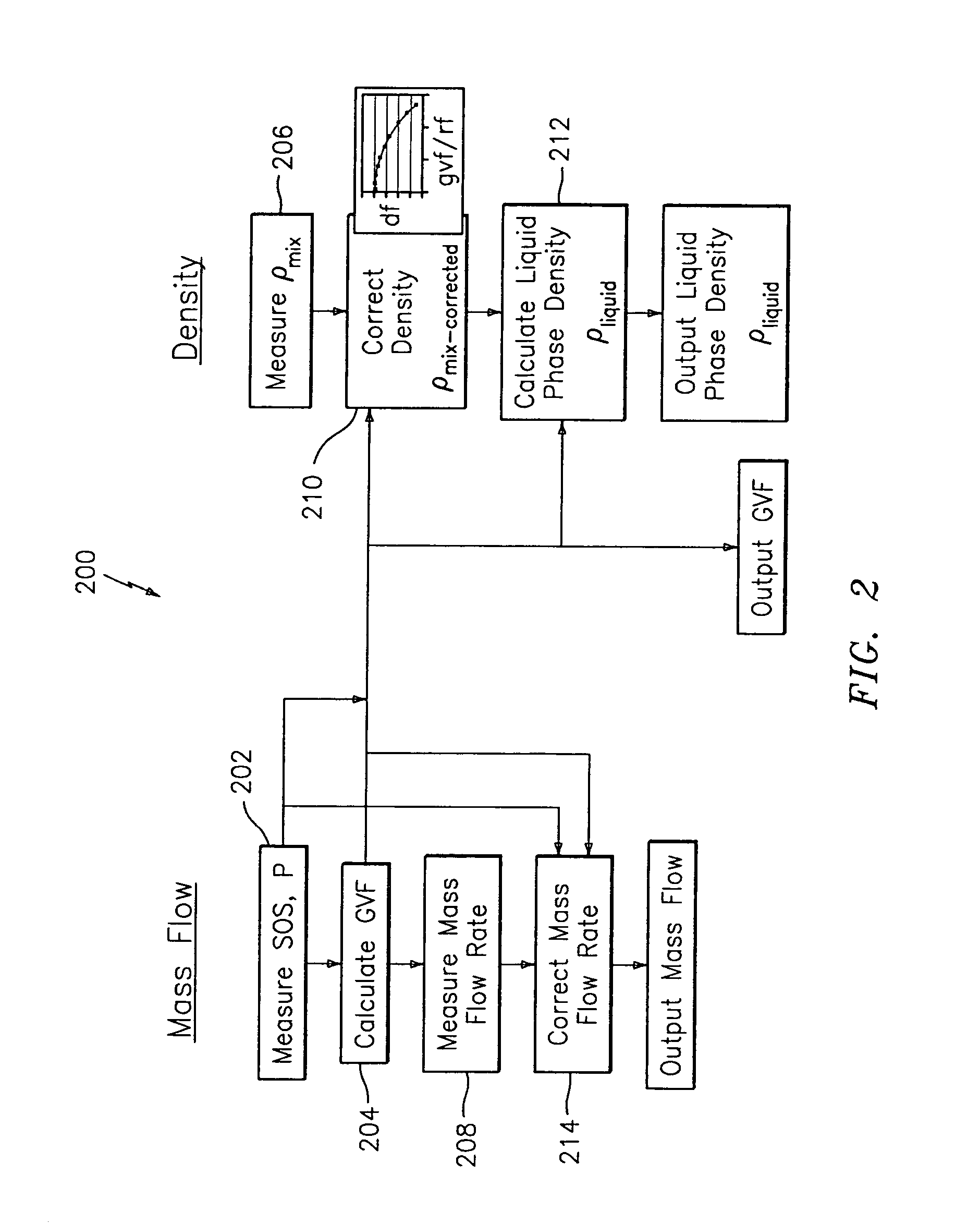
[0032]In accordance with the present invention, two processing methods for measuring the mass flow and density of the aerated fluid flow 108 are provided and illustrated in FIG. 2 and FIG. 3. Generally, the first method assumes that the performance of the density meter 122 for both the mass flow measurement and the density measurement can be augmented using the methods described in U.S. patent application Ser. No. 10 / 892,886 (CiDRA No. CC-0762), which is incorporated herein by reference. Referring to FIG. 2, a method 200 for measuring the mass flow and density of an aerated fluid flow 108 may be described as follows. A production stream 102 is directed into the multiphase separator device 104, wherein the multiphase separator device 104 separates the production stream 102 into the first fluid flow 106 and the second fluid flow 108, wherein the first fluid flow 106 is comprised mostly of gas and wherein the second fluid flow 108 is comprised mostly of liquid. The second fluid flow 10...

second embodiment

[0034]Referring to FIG. 3, a method 300 for measuring the mass flow and density of an aerated fluid flow 108 may be described as follows. As discussed hereinabove, the production stream 102 is directed into the multiphase separator device 104, wherein the multiphase separator device 104 separates the gas portion of the production stream 102 from the liquid portion of the production stream 102. The multiphase separator device 104 directs the liquid portion through the pipe 117. The density of the second fluid flow 108 is determined by measuring the pressure and speed of sound (SOSmix) through the second fluid flow 108, as shown in operational block 302. These values are then used to calculate the gas volume fraction (GVF) and / or a reduced frequency parameter of the Coriolis meter 122 operating on the second fluid flow 108, as shown in operational block 304. The speed of sound (SOSmix) may be measured by the flow meter 120 and the pressure (P) provided by a pressure sensor 126 or the ...


PUM


Abstract

A method and apparatus for measuring at least one characteristic of an aerated fluid flowing within a pipe is provided, wherein the method includes generating a measured sound speed, a measured density, a pressure and a gas volume fraction for the aerated fluid. The method also includes correcting the measured density responsive to the measured sound speed, the pressure and the gas volume fraction to generate a corrected density. The method further includes calculating a liquid phase density, determining whether the gas volume fraction is above a predetermined threshold value and generating a mass flow rate responsive to whether the gas volume fraction is above the predetermined threshold value.

Description

CROSS-REFERENCE TO RELATED APPLICATIONS[0001]The present invention claims the benefit of U.S. Provisional Patent Application Ser. No. 60 / 625,498 filed Nov. 5, 2004, which is incorporated herein by reference.TECHNICAL FIELD[0002]This invention relates generally to measuring multi-phase mixtures flowing in a pipe, and more particularly to a system for measuring an aerated multi-phase mixture flowing in a pipe.BACKGROUND[0003]Metering well head production rates is a long standing challenge for the oil and gas industry. Performing accurate and timely monitoring of the production rates has many benefits, which include optimizing overall field and specific well production.[0004]Well head monitoring represents a difficult technical challenge. The difficulty is due in no small part to the extreme variability of produced fluids which can include various types and mixtures of oil, water, gas, and solid particles.[0005]Many companies have developed various types of three phase meters design to...

Claims


Application Information

Patent Timeline
Patent Type & Authority Patents(United States)
IPC IPC(8): G01F15/08
CPCG01F1/666G01F1/74G01N9/36G01F1/86G01F15/022
Inventor GYSLING, DANIEL L.LOOSE, DOUGLAS H.
Owner EXPRO METERS
Learn More