Method of manufacturing ceramic material body

a technology of ceramic materials and body parts, applied in the direction of manufacturing tools, transformers/inductances magnetic cores, buttons, etc., can solve the problems of pin or mold breakdown, incorrect height, and inability to press properly, so as to reduce the cost, uneven filling and the effect of minimizing the non-uniform density

Inactive Publication Date: 2008-06-24
PANASONIC CORP
View PDF15 Cites 7 Cited by
  • Summary
  • Abstract
  • Description
  • Claims
  • Application Information

AI Technical Summary

Benefits of technology

[0010]The present invention allows production of excellent small ceramic elements of a complicated shape at a low cost so that uneven filling and nonuniform density thereof can be minimized.

Problems solved by technology

Unevenly filled granules cause problems, such as improper pressing, incorrect height, and moreover, breakdown of the pins or the mold.
Furthermore, in the case of a small and complicated shaped component, filling granules in every corner of the mold is difficult.
Increasing molding pressure to efficiently fill the granules causes problems, such as breakdown of the mold.
However, with the downsizing of ceramic elements, it has become difficult to satisfy the necessary conditions for ensuring the relationship between the mold size and the diameter of the ceramic granule, and powder fluidity.
However, granules tend to be filled in the multi-cavity mold more unevenly.
Therefore, it is difficult to obtain a smaller ceramic element and cost reduction thereof at the same time.

Method used


Image

  • Method of manufacturing ceramic material body
  • Method of manufacturing ceramic material body
  • Method of manufacturing ceramic material body

Examples


example 1

[0065]Alumina slurry was prepared by mixing and dispersing 96 g of alumina powder, 2 g of copper oxide, and 2 g of titanium oxide with eight grams of butyral resin, 4 g of butyl benzyl phthalate, 24 g of methyl ethyl keton, and 24 g of butyl acetate using a pot mill.

[0066]An alumina green sheet (ceramic green sheet) 0.2 mm in thickness (after being dried) was formed from the slurry using a coater. The alumina green sheet was formed on PET film.

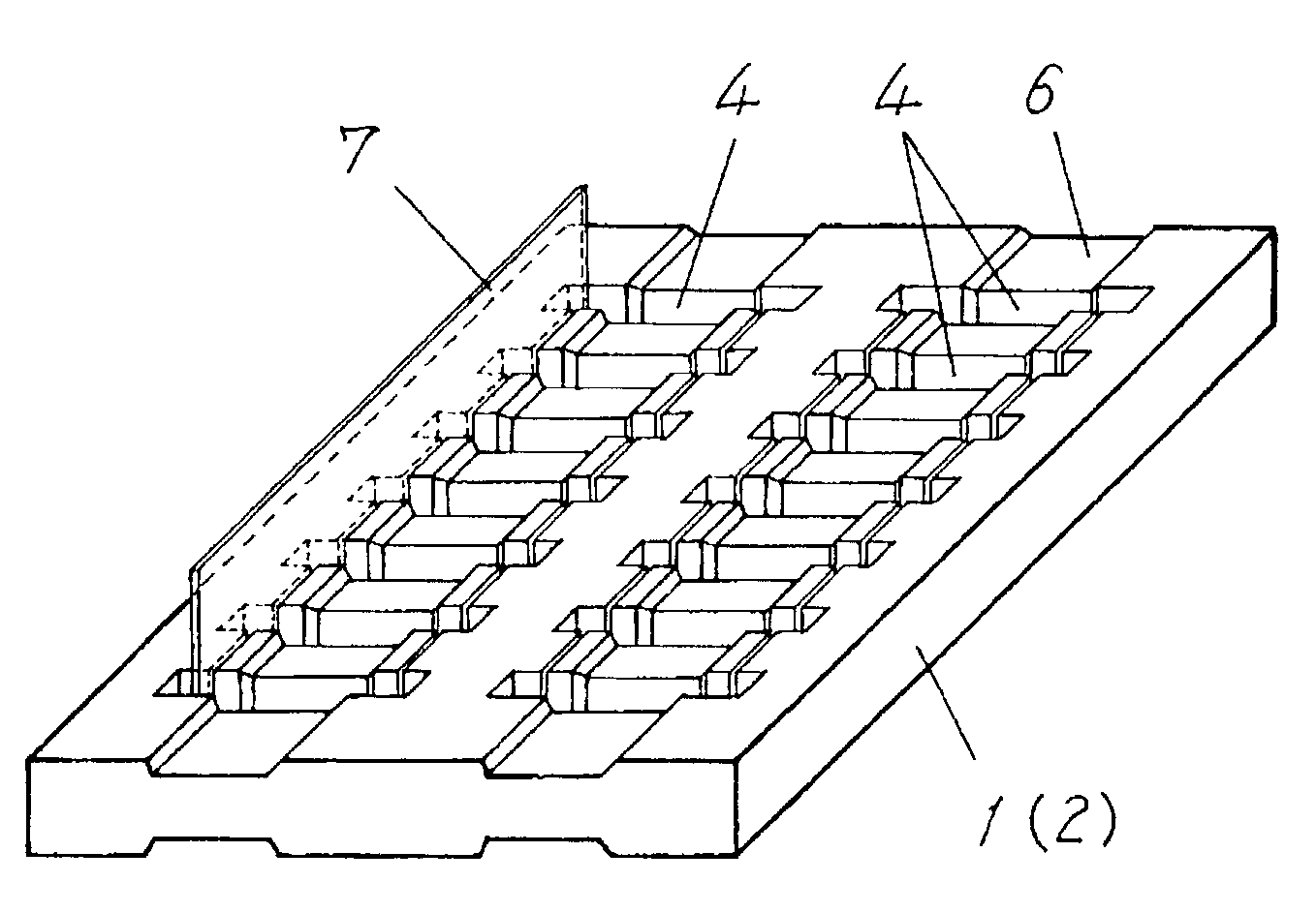
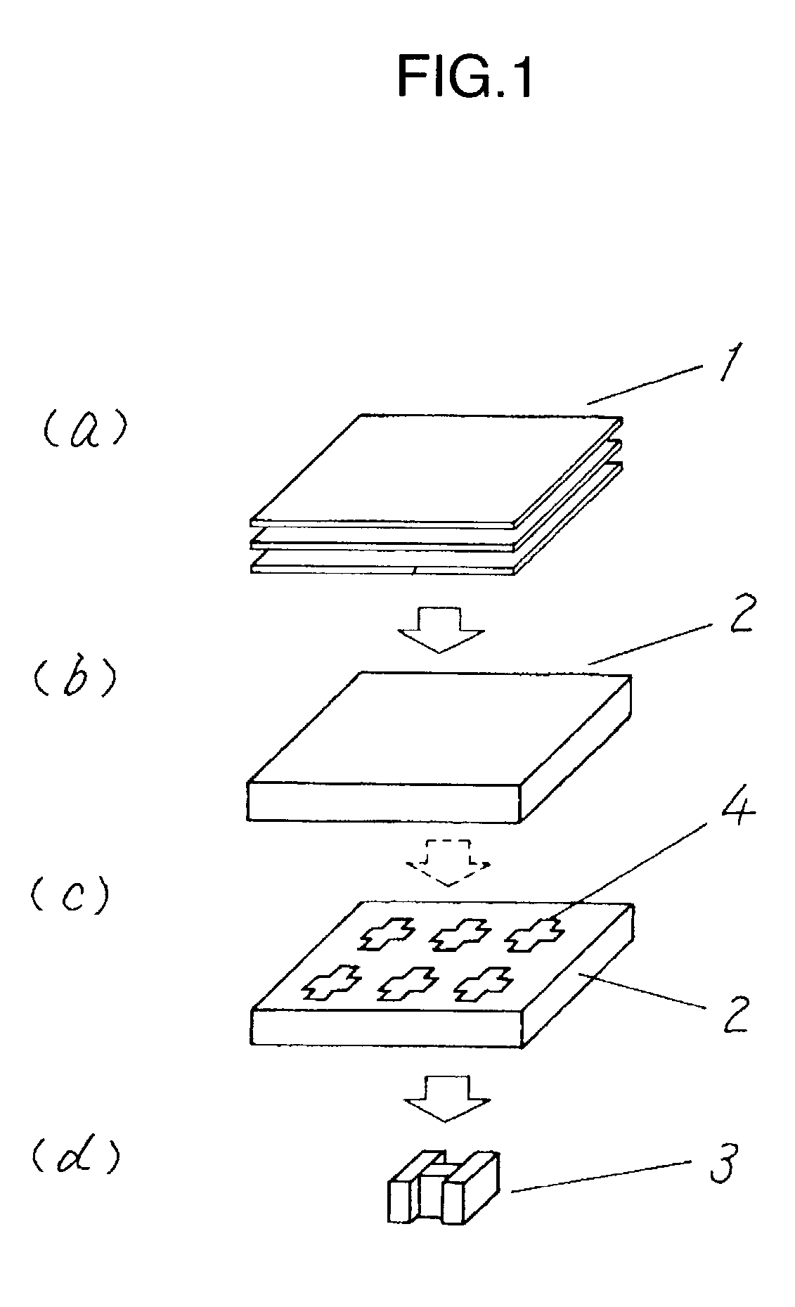
[0067]The alumina green sheet was cut into pieces, each measuring 11 cm long and 4.5 cm wide. Three pieces of the green sheet were laminated, and then punched and molded, using a mold, at the same time to form a punched molded sheet as shown in FIG. 10(a). The sectional shape of a punching pin has a cross shape. The number of pins used in the mold was 648. The mold was structured to have 8 rows of 81 pins.

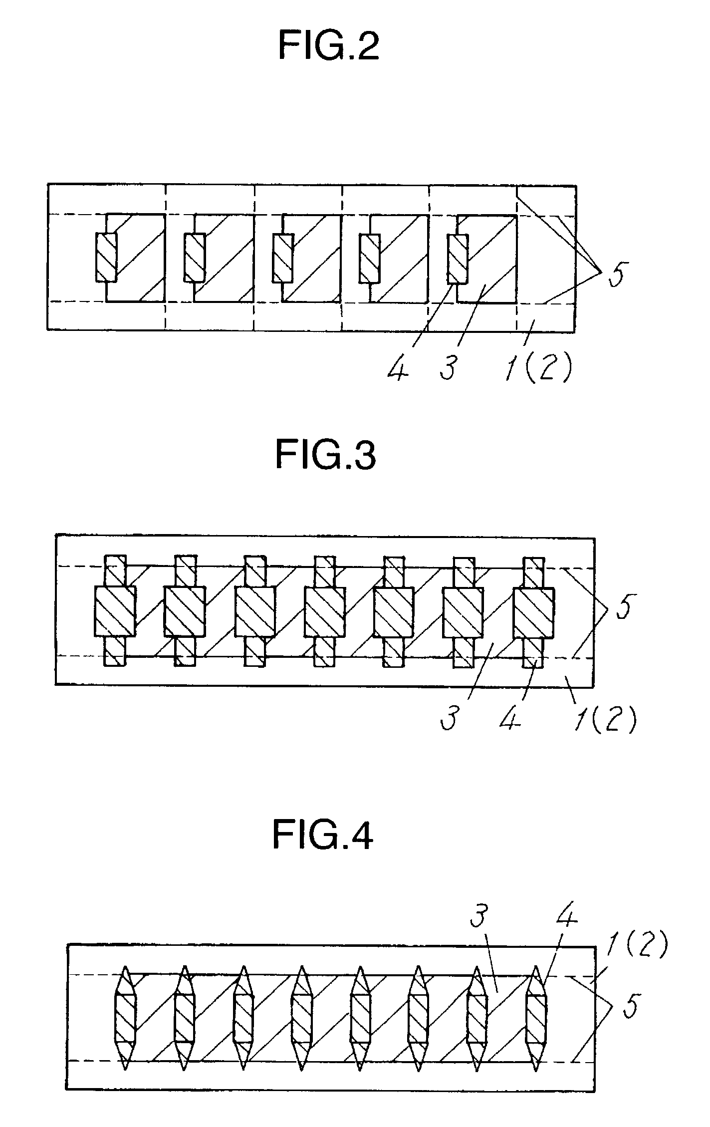
[0068]Because each of the upper and lower faces of the mold had 8 rows of projections, recesses 6 as shown in FIG. 10(a) were formed in lami...

example 2

[0071]The mold used in this example was similar to that of Example 1, except that the upper and lower faces of the mold were formed of flat surfaces. Ceramic bodies 3 were formed in a manner similar to that of Example 1, using this mold.

[0072]In the ceramic bodies (alumina bodies) produced by the method of the present invention, any defect, e.g. chip, crack, warp and insufficient filling, was not observed.

example 3

[0073]100 g of Ni—Zn—Cu ferrite powder was mixed with eight grams of butyral resin, 4 g of butyl benzyl phthalate, 24 g of methyl ethyl keton, and 24 g of butyl acetate and kneaded using a pot mill to prepare ferrite slurry.

[0074]A ferrite green sheet 0.2 mm in thickness (after being dried) was formed from this slurry, using a coater. The ferrite green sheet was formed on PET film.

[0075]Ceramic bodies made of ferrite were formed using this ferrite green sheet, in the manner as in Example 1. The ceramic bodies were sintered under the condition that a sintering temperature of 900° C. was maintained for two hours.

[0076]In the ceramic bodies 3 (ferrite elements) produced by the method of the present invention, any defect, e.g. chip, crack, warp and insufficient filling, was not observed.


PUM

PropertyMeasurementUnit
diametersaaaaaaaaaa
thicknessaaaaaaaaaa
molding pressureaaaaaaaaaa

Abstract

A method of manufacturing ceramic bodies comprising the steps of: preparing a ceramic sheet; forming through holes in the ceramic sheet, each of the through hole forming at least one part of the contour of each ceramic bodies; and cutting the ceramic sheet into pieces of ceramic bodies. The ceramic sheet can be a single ceramic sheet or a laminate of ceramic sheets. The method of manufacturing ceramic bodies further comprises a step of forming a recess in the ceramic sheet, or pressure molding or partially removing of the ceramic body, as required. The manufacturing method provides inexpensive production of small ceramic elements having a complicated shape and extremely smooth surfaces with less uneven filling and nonuniform density.

Description

FIELD OF THE INVENTION[0001]The present invention relates to a method of manufacturing ceramic bodies for use in bobbins, core materials, or base materials of electronic components.BACKGROUND OF THE INVENTION[0002]Electronic components have found wide applications in various kinds of electronic equipment and communication devices. With recent size and cost reduction of electronic components, it is becoming more important to reduce the size and cost of ceramic elements for use in bobbins, core materials, or base materials thereof as well.[0003]Conventionally, these ceramic bodies have been manufactured by powder molding. The powder molding process includes the steps of: adding a binder to a ceramic raw material; forming ceramic granules in a granulation process; filling the ceramic granules in a mold; molding the granules by uniaxially pressing followed by a sintering of the molded object.[0004]In the powder molding process, ceramic granules must be filled in a mold evenly. Unevenly ...

Claims


Application Information

Patent Timeline
Patent Type & Authority Patents(United States)
IPC IPC(8): B28B3/00C04B35/64H01F17/03B28B3/02B28B11/10B28B11/12B28B11/14B28B11/16
CPCB28B11/10B28B11/14B28B11/168
Inventor IBATA, AKIHIKOOBA, MICHIOYOSHIZAWA, TOSHIHIRO
Owner PANASONIC CORP
Why Eureka
Try Eureka