Scanning probe microscope

a scanning probe and microscope technology, applied in the direction of mechanical measurement arrangement, mechanical roughness/irregularity measurement, instruments, etc., can solve the problems of time-consuming practice of replacing scanners and subsequent changing settings, and difficulty in ensuring both a relatively large observation range and a high resolution at the same tim

Inactive Publication Date: 2008-06-24
SHIMADZU CORP
View PDF2 Cites 4 Cited by
  • Summary
  • Abstract
  • Description
  • Claims
  • Application Information

AI Technical Summary

Benefits of technology

[0020]For example, in the first aspect of the SPM of the present invention, the probe moving device with a small movable range (i.e., a small maximum scan range) in the X-Y axis direction and a sample moving device with a large movable range (i.e., a large maximum scan range) in the X-Y axis direction can be switched alternatively. The former one is used for observing in a narrow range, while the latter one is used for observing in a wide range. Therefore, replacing scanners according to the observed targets or purposes as before can be precluded to conserve the time for replacing scanners or changing settings.
[0022]In the third aspect of the SPM of the present invention, a position sensor is provided, for detecting a position of the sample moving device with a large movable range in the X-Y axis direction, and for feedback controlling the sample moving device according to the position information. The non-linearity of the scanner is thereby compensated, and a linear image is obtained when scanning in a wide range.

Problems solved by technology

That is, it is generally difficult for a scanner with a relatively large maximum scan range to yield an image with a high resolution.
Accordingly, it is difficult to ensure both a relatively large observation range and a high resolution at the same time.
However, a problem in which the time-consuming practice of replacing scanners and the subsequent changing of settings will occur.
Consequently, it is difficult to make observation at high resolution.
However, when a small scanner is used for observation with a high resolution, and as the maximum scan range being smaller, the displacement of the field of view cannot be completely corrected during a long observation period.

Method used


Image

  • Scanning probe microscope
  • Scanning probe microscope
  • Scanning probe microscope

Examples


embodiment 1

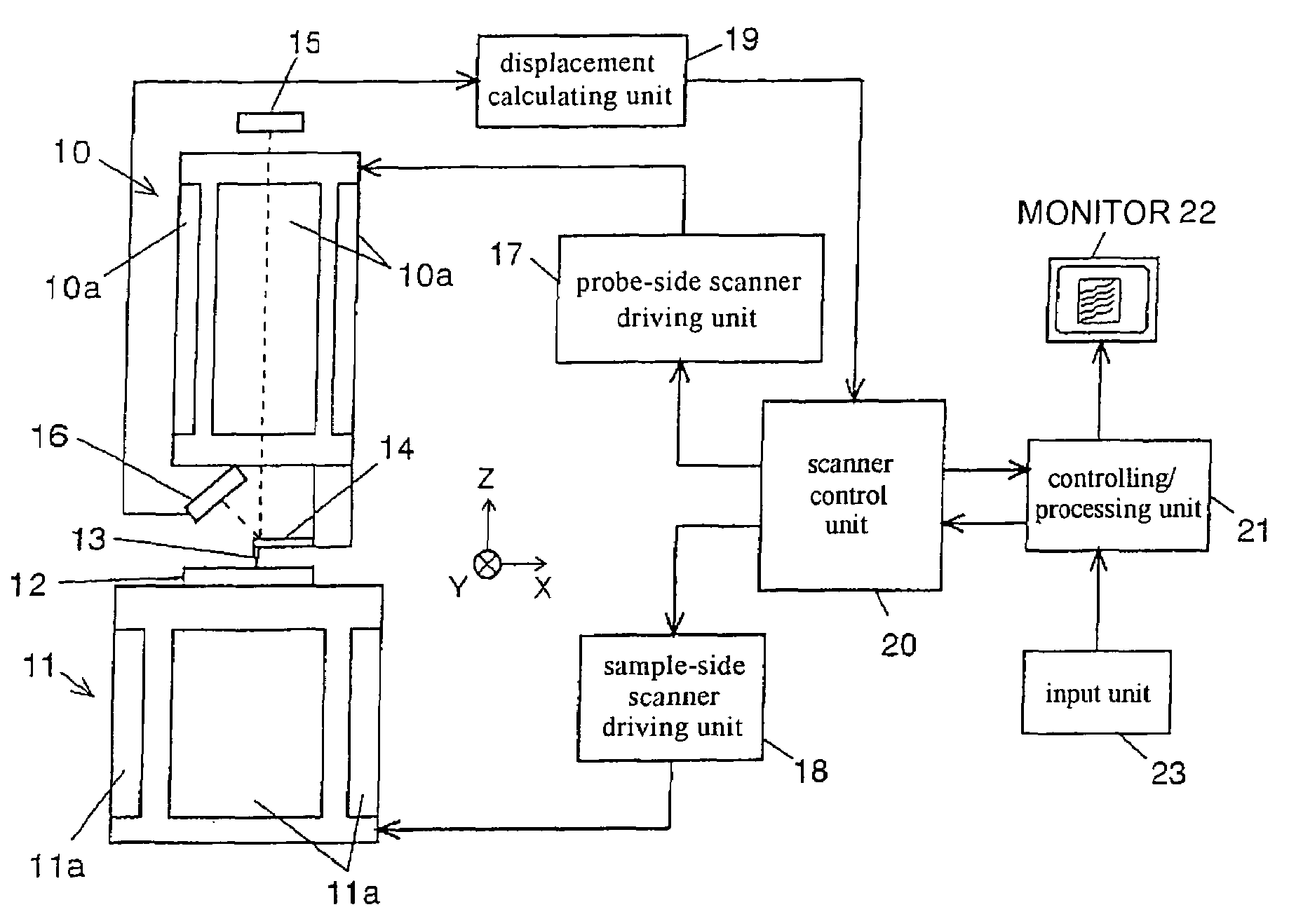
[0032]FIG. 1 shows a schematic structure of a SPM i.e., an atomic force microscope (AFM) according to the embodiment of the present invention. The AFM of this embodiment is provided with a sample-side scanner 11 with a sample 12 mounted thereon. The sample-side scanner 11 is used for scanning the sample 12 in the X-Y axis directions and moving the sample 12 in the Z-axis direction. The AFM of this embodiment is further provided with a probe-side scanner 10 disposed on a cantilever 14 with a probe 13, wherein the probe-side scanner 10 is used for scanning the probe 13 in the X-Y axis direction, and moving the probe 13 in the Z-axis direction.

[0033]The maximum scan range of the probe-side scanner 10 is different from that of the sample-side scanner 11. A scanner with a relatively large maximum scan range (scanner used for wide-range scanning) is used as the sample-side scanner 11, and a scanner with a relatively small maximum scan range (scanner used for narrow-range scanning) is used...

embodiment 2

[0042]The AFM of this embodiment is provided with a position sensor 24, for detecting a position of the sample-side scanner 11 in the AFM of the Embodiment 1. With this configuration, a signal from the position sensor 24 can be fed back to the scanner control unit 20, for compensating the scale error caused by the non-linearity of the piezoelectric elements. According to the AFM of this embodiment, as described above, even though the sample-side scanner 11 and the probe-side scanner 10 are used together to perform a wide range observation at high resolution, the sample 12 can move in wide range while maintaining a linear state. Therefore, it is possible to correctly position the sample and observe the sample at high resolution, which is difficult to achieve with the prior art.

[0043]Although the preferable configurations for implementing the present invention have already been illustrated through the embodiments, the present invention is not limited to the embodiments described above...


PUM

PropertyMeasurementUnit
scanning probe microscopeaaaaaaaaaa
physical quantityaaaaaaaaaa
displacement magnitudeaaaaaaaaaa

Abstract

A scanning probe microscope (SPM) is provided capable of a narrow to a wide range observation according to observed targets or purposes without replacing a scanner while maintaining a high resolution. The SPM is provided with a probe-side scanner 10 and a sample-side scanner 11. The probe-side scanner 10 is to move the probe 13 in X-, Y-, Z-axis directions, and the sample-side scanner 11 is to move the sample 12 in the X-, Y-, Z-axis directions. A scanner with a small maximum scan range is used as the probe-side scanner 10; a scanner with a large maximum scan range is used as the sample-side scanner 11; and both can be switched between each scanner for use according to the observed targets or purposes. Alternatively, the probe-side scanner 10 is used for scanning in a narrow range, and the sample-side scanner 11 is used to move the field of view.

Description

BACKGROUND OF THE INVENTION[0001]1. Field of Invention[0002]The present invention relates to a scanning probe microscope (SPM).[0003]2. Description of Related Art[0004]A scanning probe microscope (SPM) scans a sample surface with a tiny probe, and detects an interaction between the tiny probe and the sample, so as to detect and to image a shape or physical quantity of the sample surface. One type of the SPM is scanning tunneling microscope (STM), in which the type of interaction measured is an electrical current flowing between the probe and the sample. Another type of the SPM includes atomic force microscope (AFM), in which the atomic force between the probe and the sample is monitored.[0005]FIG. 3 shows a structure of the major parts of a conventional AFM (for example, referring to Japanese Laid-Open Application No. 2000-338027 ([0003], [0004], FIG. 7)). The conventional AFM includes a cantilever 34 with a sharp probe 33 at the front end, a displacement detection system for detect...

Claims


Application Information

Patent Timeline
Patent Type & Authority Patents(United States)
IPC IPC(8): G01N23/00G01N13/16G01B21/30G01Q10/02G01Q10/04G01Q30/06
CPCB82Y35/00G01Q20/02G01Q10/06G01Q10/04F16B37/047B21K1/68
Inventor OHTA, MASAHIRO
Owner SHIMADZU CORP
Why Eureka
Try Eureka