
Arc/spark optical emission spectroscopy correlated with spark location

a technology of optical emission and correlation, applied in the field of optical emission spectroscopy, can solve the problems of no method for determining, blackening of strike points, and inability to correlate the position of individual sparks with the elemental composition of materials,

Inactive Publication Date: 2008-06-24
THERMO NITON ANALYZERS
View PDF18 Cites 4 Cited by
  • Summary
  • Abstract
  • Description
  • Claims
  • Application Information

AI Technical Summary

Benefits of technology

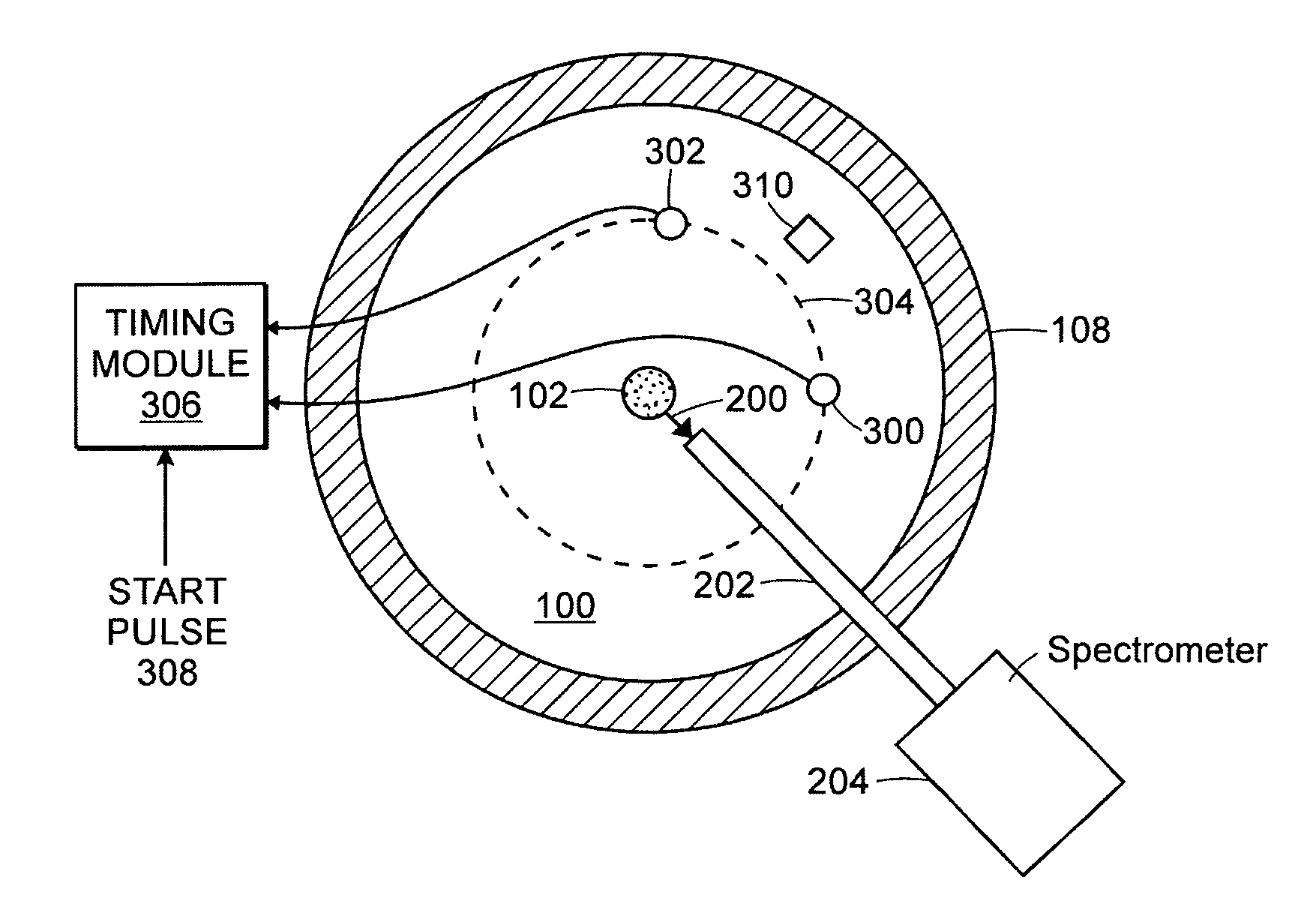
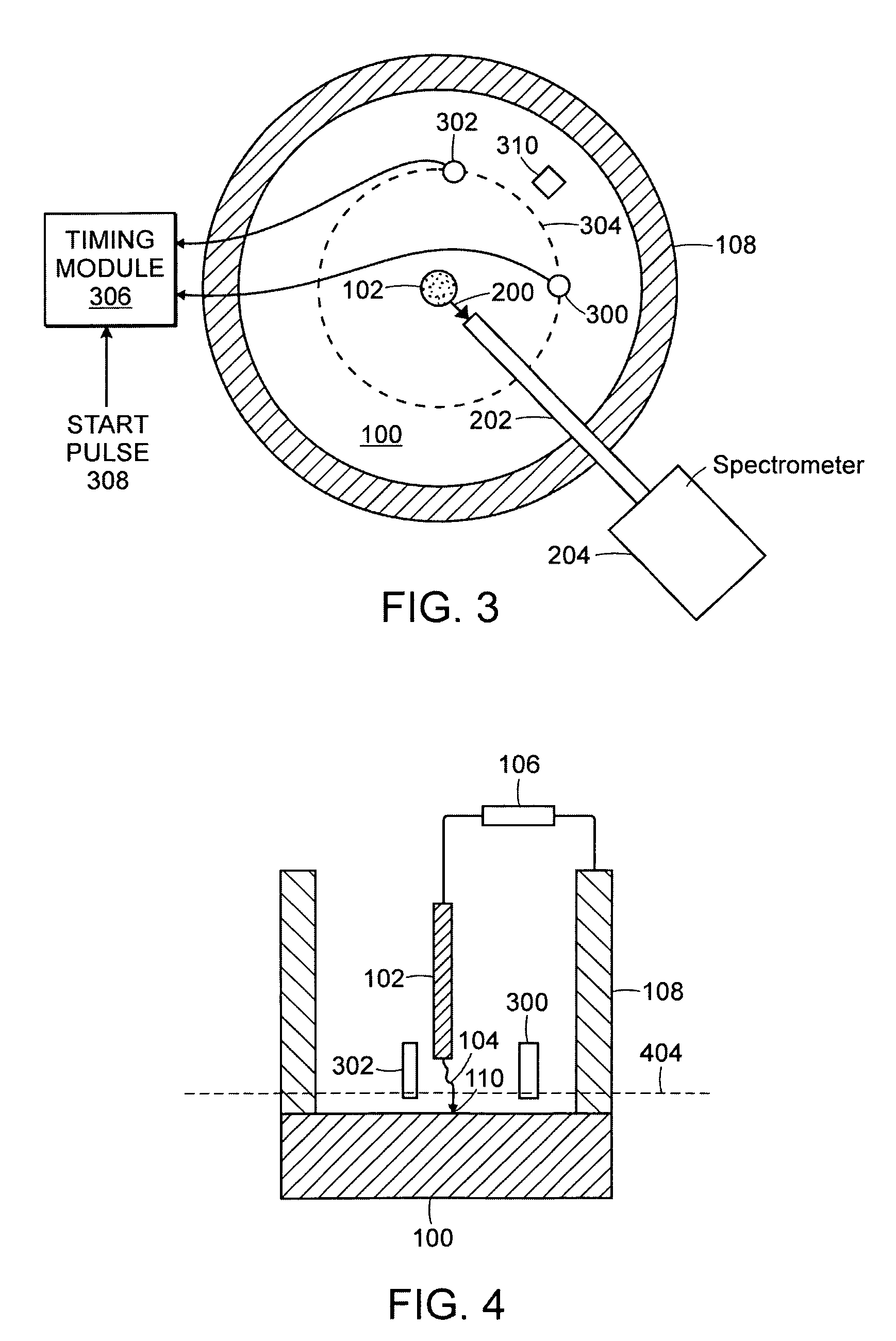
"The present invention provides an apparatus and method for analyzing the composition of a sample and determining the location on the sample where the analysis is performed using an excitation beam. The apparatus includes a beam generator for exciting the sample and a spectrometer for generating a spectrum from the optical signal produced by the sample. The apparatus also includes at least two microphones for detecting the sound produced by the sample. The method involves producing an excitation beam and detecting the sound produced by the sample. The apparatus and method can be used in various applications, such as analyzing the composition of a sample or identifying the location of a sound source."

Problems solved by technology

This large number of spark strikes typically leaves a blackened area of strike points.
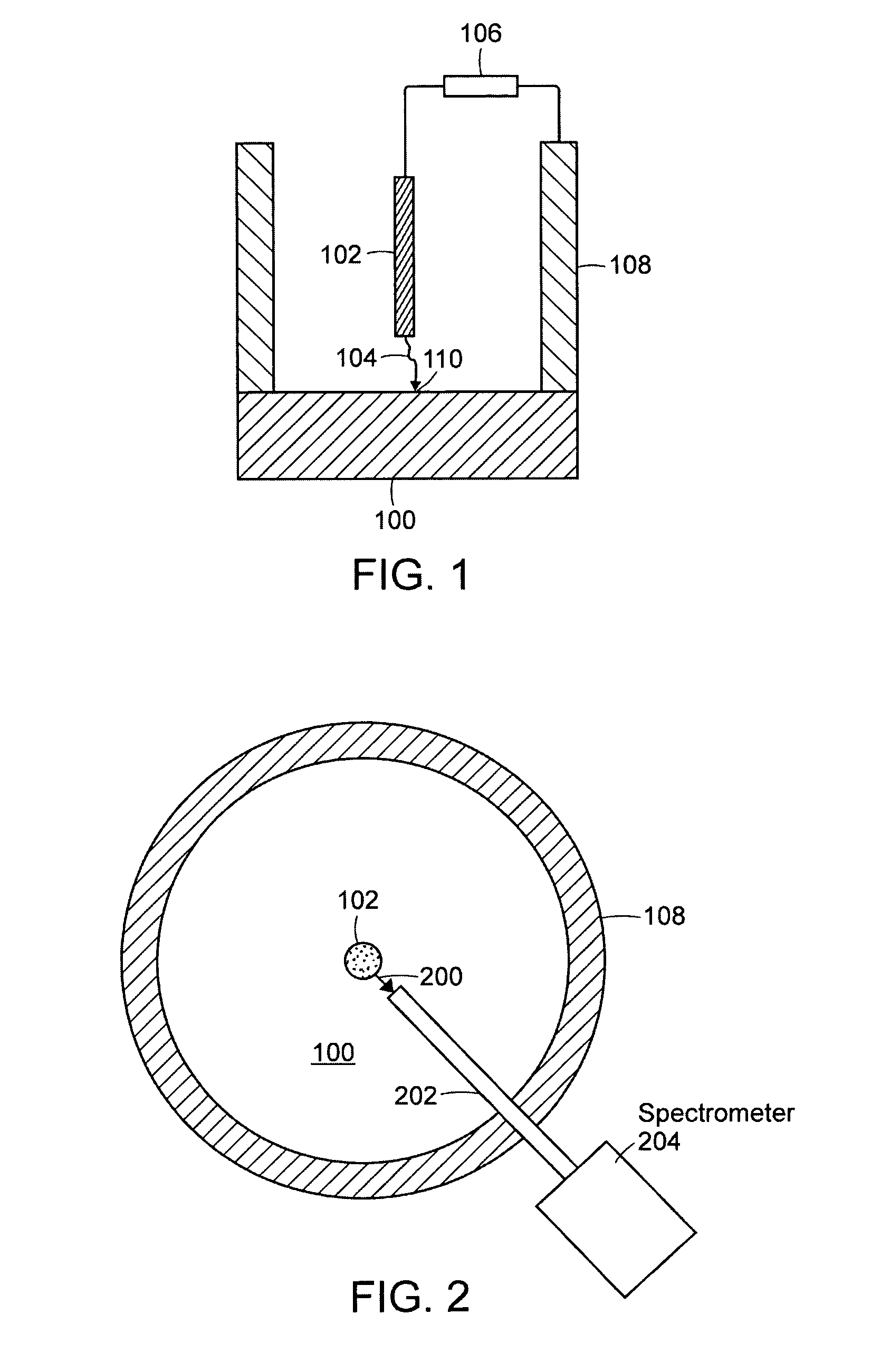
At this time, however, no method exists for determining where an individual spark strikes the sample 100 and, hence, the position of an individual spark cannot be correlated with the elemental composition of the material excited by the spark.

Method used


Image

  • Arc/spark optical emission spectroscopy correlated with spark location
  • Arc/spark optical emission spectroscopy correlated with spark location
  • Arc/spark optical emission spectroscopy correlated with spark location

Examples


Embodiment Construction

[0040]Embodiments of the present invention include methods and systems for determining where an individual spark strikes a sample in an OES arc / spark apparatus. Other embodiments of the present invention include methods and systems for correlating the position of an individual spark with the elemental composition of the material excited by the spark. The methods and systems described herein can determine the spatial distribution of elemental composition with great spatial resolution, such as within microns. Devices, according to the present disclosure, for making spatially correlated elemental analysis can be added to present instrumentation.

[0041]Other embodiments of the present invention include methods and systems for determining a time at which a spectrum of interest is produced or which of a plurality of spectra is of interest.

[0042]Yet other embodiments of the present invention include methods and systems for correlating the position of an individual spark with the elemental c...


PUM

PropertyMeasurementUnit
sound speedaaaaaaaaaa
speedaaaaaaaaaa
radiusaaaaaaaaaa

Abstract

Two or more high-frequency microphones are used to determine where an individual spark or other excitation beam strikes a sample in an optical emission spectroscopy (OES) instrument. The position of the spark can be correlated with the elemental composition of the material in the sample vaporized by the spark. The microphones are placed appropriately in air around a sparker of the instrument, or appropriately on the sample, or on both the sample and in the air. Arrival times of sound from the spark to the microphones, or a difference in the arrival times, yields information, from which the position of the spark relative to the microphones, and hence the absolute position of the spark, is deduced, such as by triangulation. Optionally or in addition, a signal that indicates a time when the spark is produced is correlated with one or more spectra detected by a spectrometer, so a spectrum that results from the vaporized sample can be distinguished from a spectrum that results from heated gas above the sample.

Description

[0001]The present application claims priority from U.S. Provisional Patent Application, Ser. No. 60 / 700,664, filed c. Jul. 20, 2005, which is incorporated herein by reference.TECHNICAL FIELD[0002]The present invention relates to optical emission spectroscopy (OES) and, more particularly, to methods and devices for using acoustic measurements concomitant with surface ablation to obtain spatially resolved elemental analysis based on arc / spark optical emission spectroscopic techniques.BACKGROUND ART[0003]Optical emission spectroscopy (OES) is a mature, robust technology for the elemental analysis of materials. For metals, the prevalent techniques for generating an emission spectra use either an electric arc or a spark, or both, (collectively hereinafter “spark”) to vaporize a small quantity of a sample to be analyzed. A survey of OES analytical techniques may be found in Slickers, Automatic Atomic-Emission Spectroscopy, Second Edition (1993), which is incorporated herein by reference.[...

Claims


Application Information

Patent Timeline
Patent Type & Authority Patents(United States)
IPC IPC(8): G01J3/443G01N21/17G01N21/63G01N21/67
CPCG01N21/1702G01N21/67G01N21/718G01N29/0618G01N29/14G01N29/2418G01N33/20G01S5/26G01S5/30G01N21/94G01N2021/1706G01N33/202
Inventor GRODZINS, LEE
Owner THERMO NITON ANALYZERS
Learn More