Speedometer drive apparatus and method

a technology of speedometer and drive device, which is applied in the direction of instruments, digital computer details, devices using time traversed, etc., can solve the problems of inaccurate speed and odometer readings, no mechanical speedometer's rotating cable, and immaterial time it takes to achieve the effect of rotation measuremen

Inactive Publication Date: 2008-06-24
R & G SPECIALTY PROD
View PDF11 Cites 8 Cited by
  • Summary
  • Abstract
  • Description
  • Claims
  • Application Information

AI Technical Summary

Benefits of technology

[0019]The present invention includes a method and apparatus for accurately driving any mechanical, cable-driven analog speedometer instrument, accounting for any change in drive train components that would otherwise render the speedometer instrument readings inaccurate, such as changes in gearing or tire size. An advantage of the present invention includes embodiments that can be easily installed even by the layman; and once such a unit is installed, it can be quickly and easily recalibrated as needed upon subsequent repair or modification involving changes to the vehicle's drive train components, at no further cost, without the need to move the vehicle, and without the need of any special knowledge or equipment.
[0020]In a first aspect the present invention includes a speed determining apparatus for a vehicle having a set of road wheels and a mechanical speedometer, where the apparatus includes a motor mounted to the mechanical speedometer, a shaft encoder operatively fitted to the motor to facilitate the measurement of rotation by the motor, a sensor capable of sensing rotation of one of the road wheels and an electronic control circuit electronically connected to the shaft encoder and the sensor. The electronic control circuit is monitors the sensor and determines road wheel speed. The electronic control circuit also monitors the shaft encoder and controls the speed of the motor in response to the determined wheel speed. The electronic control circuit is structured and arranged to display visual indicia based upon a location of a mechanical pointer on the face of the speedometer instrument combined with the measured rotation of the motor by the shaft encoder.
[0021]In some embodiments the motor is mounted to the speedometer via a self aligning mechanical mount. In some embodiments the speed determining apparatus includes at least one memory device with a first software program stored on the memory device, where the first software program includes instructions to perform a measured mile routine. The memory device may also include a second software program stored on the memory device, where the second software program includes instructions to perform a road wheel calibration routine. The memory device may also include a third software program stored on the memory device, where the third software program includes instructions to perform a motor coder routine. The memory device may also include a fourth software program stored on the memory device, where the fourth software program includes instructions to perform a speedometer calibration routine.
[0022]In a second aspect the present invention includes a method for calibrating a speedometer instrument having a shaft encoder, where the method includes determining a calibration constant of the speedometer instrument by initiating a set program for the speedometer instrument, determining an elapsed time of about 1 complete shaft encoder pulse and storing the elapsed time in a digital storage medium and iteratively comparing the elapsed time to values on a calibration table until a matched speed is found. The method also includes determining the location of a pointer on the speedometer, comparing the location of the point relative to the matched speed in the digital recording medium and comparing the location of the pointer with that of the matched speed.
[0023]In some embodiments the method includes determining the elapsed time of 1 complete shaft encoder pulse by receiving a first positive encoder signal, receiving a second positive encoder pulse edge signal and determining an elapsed time of about 1 / 32 revolutions based upon the first and second positive encoder signals.
[0024]In some embodiments the location of the pointer a physical location on a mechanical speedometer. In some embodiments the location of the pointer is represented by an electric signal from an electronic speedometer.

Problems solved by technology

Since this is a “distance only” measurement, the time it takes to accomplish it is immaterial.
None of these technologies employ the mechanical speedometer's rotating cable.
Something as simple as a change in tire size when replacing worn tires will render inaccurate the speed and odometer readings of not just the mechanical speedometer, but also the other types of speedometer outlined above.
A universal problem facing owners of vehicles with mechanical speedometers is keeping the speedometer instrument readings accurate in the face of vehicle repairs, upkeep, or custom modifications involving the various components of the drive train.
Although there are methods to regain the accuracy of the speedometer instrument in any given situation, the means to do so is labor-intensive, time-consuming and generally expensive, involving the services of specialists who maintain facilities and equipment specifically designed for this purpose.
Even if these expensive and time-consuming methods are employed, further modifications to the vehicle's drive train components may and likely will again render the speedometer inaccurate; and will require yet another investment of time and money to, yet again, correct the problem.
Many people choose to live with speedometers that are mildly to grossly inaccurate simply because of the difficulty and expense in keeping them accurate.

Method used


Image

  • Speedometer drive apparatus and method
  • Speedometer drive apparatus and method
  • Speedometer drive apparatus and method

Examples


Embodiment Construction

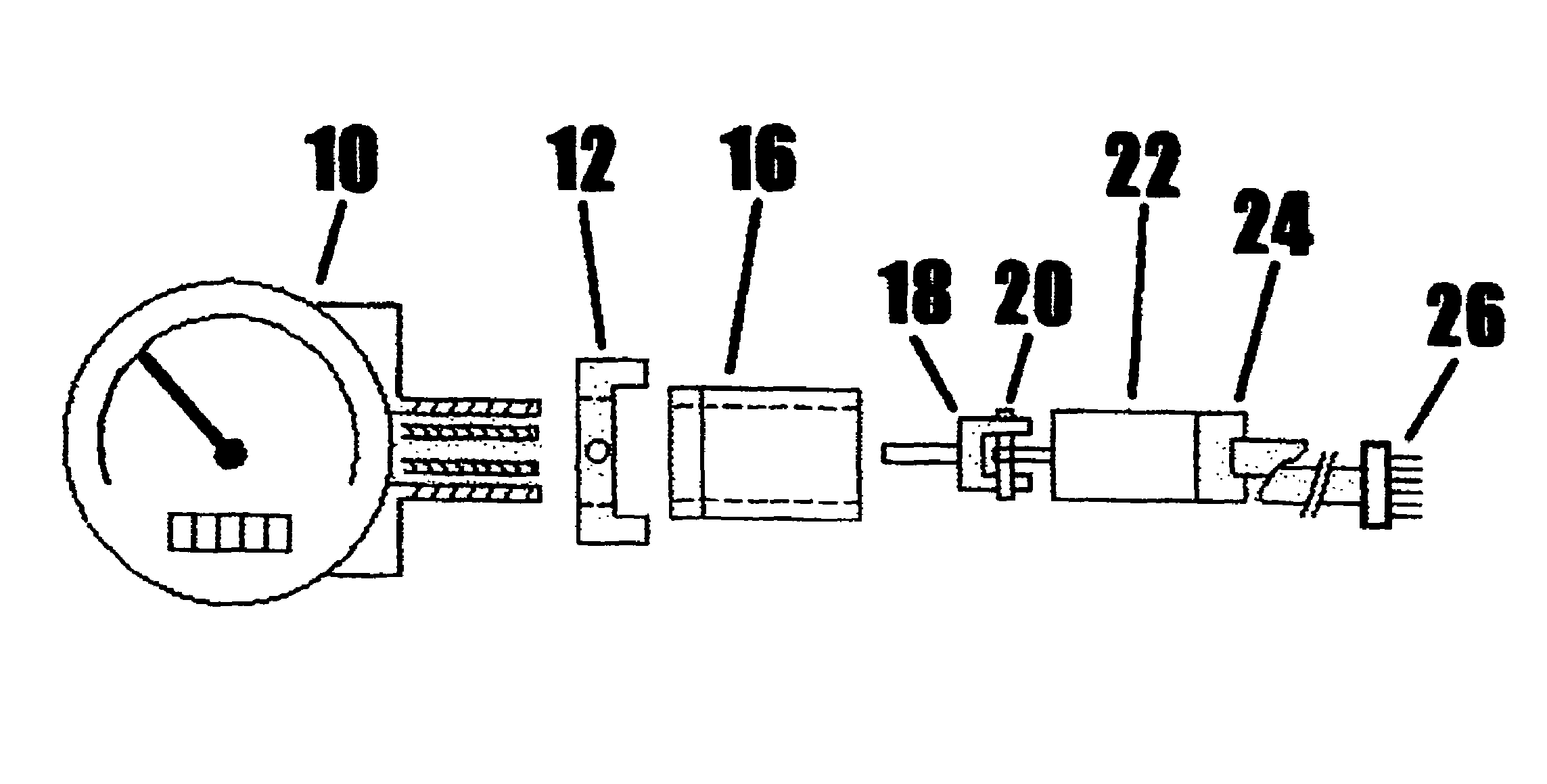
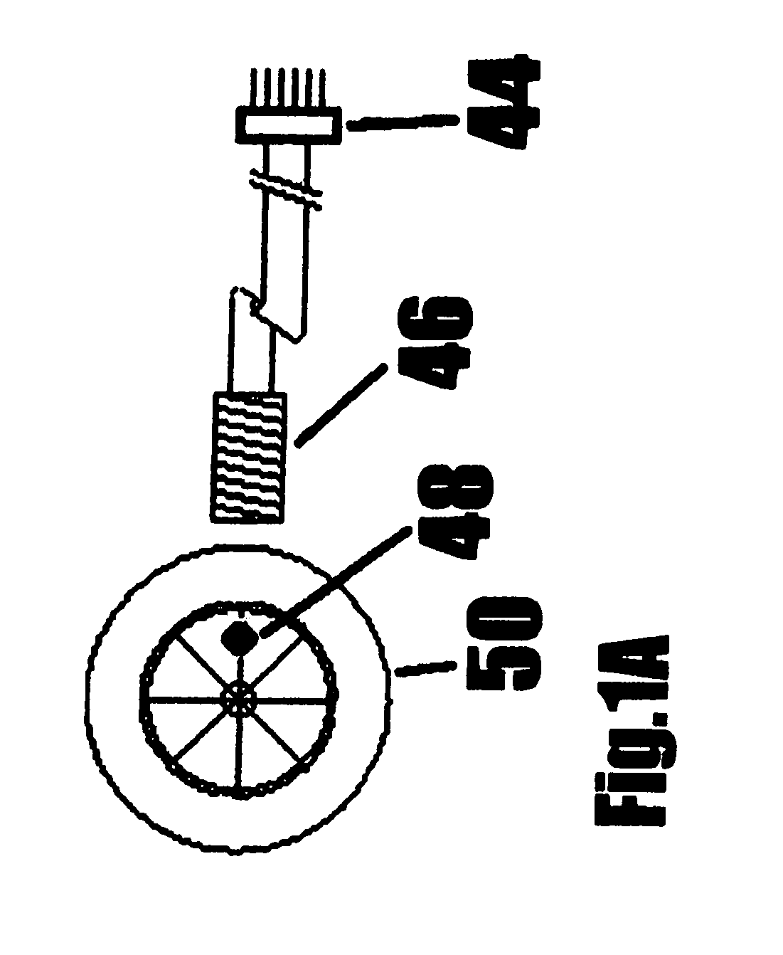
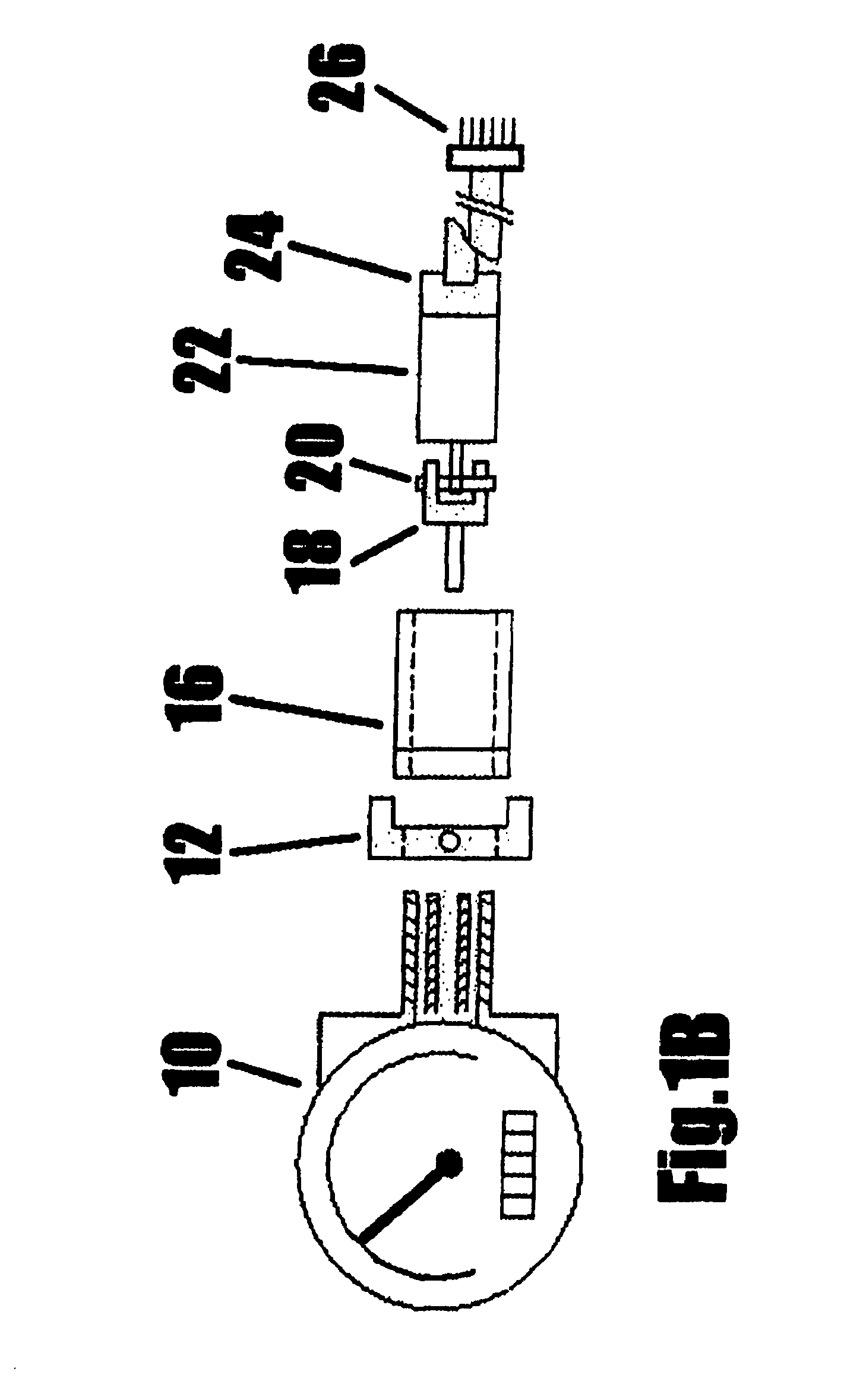
[0036]The present disclosure will now be described more fully with reference to the Figures in which an embodiment of the present disclosure is shown. The subject matter of this disclosure may, however, be embodied in many different forms and should not be construed as being limited to the embodiments set forth herein.

[0037]In the subsequent discussion of the invention, “look-up tables” will be mentioned. There are three such tables. One is a reference table that contains the “one rotation pulse width” in microseconds, of a reference size tire for each of 255 speeds from 1 mph to 255 mph. This table is included as part of the control program and is referred to as the “reference table”. The remaining tables are generated during the “calibration” of the device. The first such table gives the computer program sufficient information about the specific speedometer being used. This is referred to as the “speedometer look-up table”. The second table is specific to the tire size being emplo...


PUM


Abstract

An automotive speedometer drive apparatus is disclosed that replaces an existing speedometer cable of the type used to drive mechanical speedometer instruments. The drive being an electronically controlled motor made to rotate at the correct rate to give an accurate speed indication, taking into consideration the specific tire size and specific speedometer involved. The drive may also be easily installed and field-calibrated by the user without the need of any special knowledge or equipment.

Description

BACKGROUND OF THE INVENTION[0001]1. The Field of the Present Invention[0002]The present invention relates generally to the field of automotive instrumentation, and more specifically to an apparatus and method for accurately driving any mechanical cable-driven speedometer instrument, as is typically found on older vehicles.[0003]2. General Background[0004]For the purposes of this application, the terms “processor”, “microprocessor”, “controller”, “microcontroller” or equivalent terminology are meant to be synonymous unless otherwise stated. Likewise, the terms “automobile”, “truck”, “vehicle”, or equivalent terminology are meant to be interchangeable unless otherwise stated. References made in the English measurement system are hereafter assumed to include their metric equivalent values and vice versa.[0005]One of the principal instruments in all motor vehicles is the speedometer. It is universally recognized that knowing how fast one is driving is an important aspect of operating th...

Claims


Application Information

Patent Timeline
Patent Type & Authority Patents(United States)
IPC IPC(8): G01P21/02
CPCG01P1/04G01P3/487G01P3/64G01P21/02
Inventor ROMANO, JAMES P.
Owner R & G SPECIALTY PROD
Why Eureka
Try Eureka