Multiple stage personal fall arrest energy absorber

a technology of energy absorber and multi-stage, which is applied in the direction of safety belts, sports equipment, cleaning equipment, etc., can solve the problems of shock absorber not fully extended, misused individuals in the field, severe injury to the person relying on the lanyard for safety, etc., and achieves the effect of reducing the number of peopl

Active Publication Date: 2008-07-01
RELIANCE INDUSTRIES LIMITED
View PDF4 Cites 32 Cited by
  • Summary
  • Abstract
  • Description
  • Claims
  • Application Information

AI Technical Summary

Benefits of technology

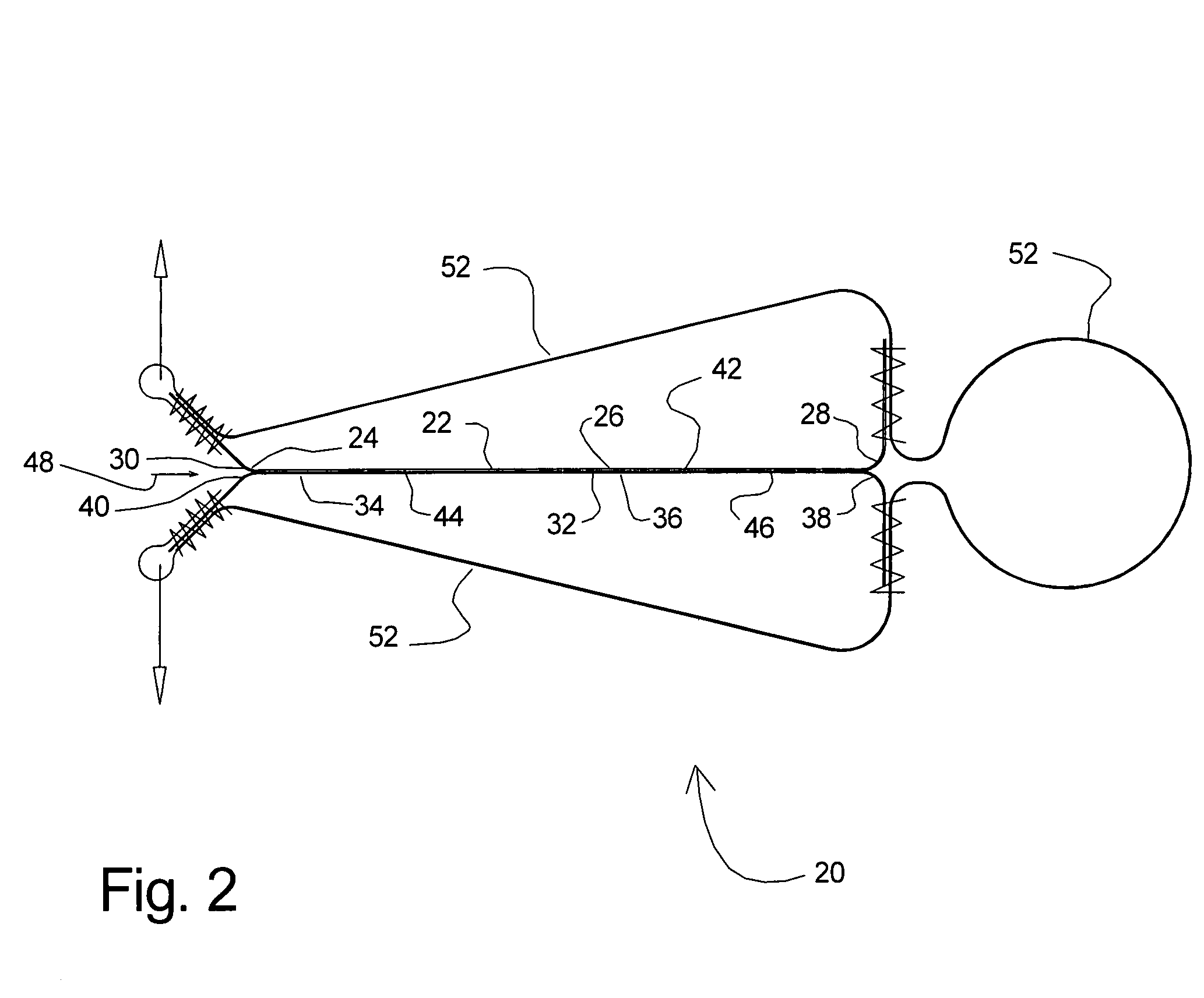
[0018]It is further contemplated that the shock absorber will provide a deceleration force by the tearing away of the connection between the first strap and the second strap. Preferably, the connection between first strap and the second strap is accomplished by stitching or weaving the two straps together. The area of higher strength, or the differences in strength, may be achieved by varying the density of stitching or woven threads that joins the two straps. Thus, the first stage area of lower strength w

Problems solved by technology

A significant drawback to these devices is that they are often misused by individuals in the field.
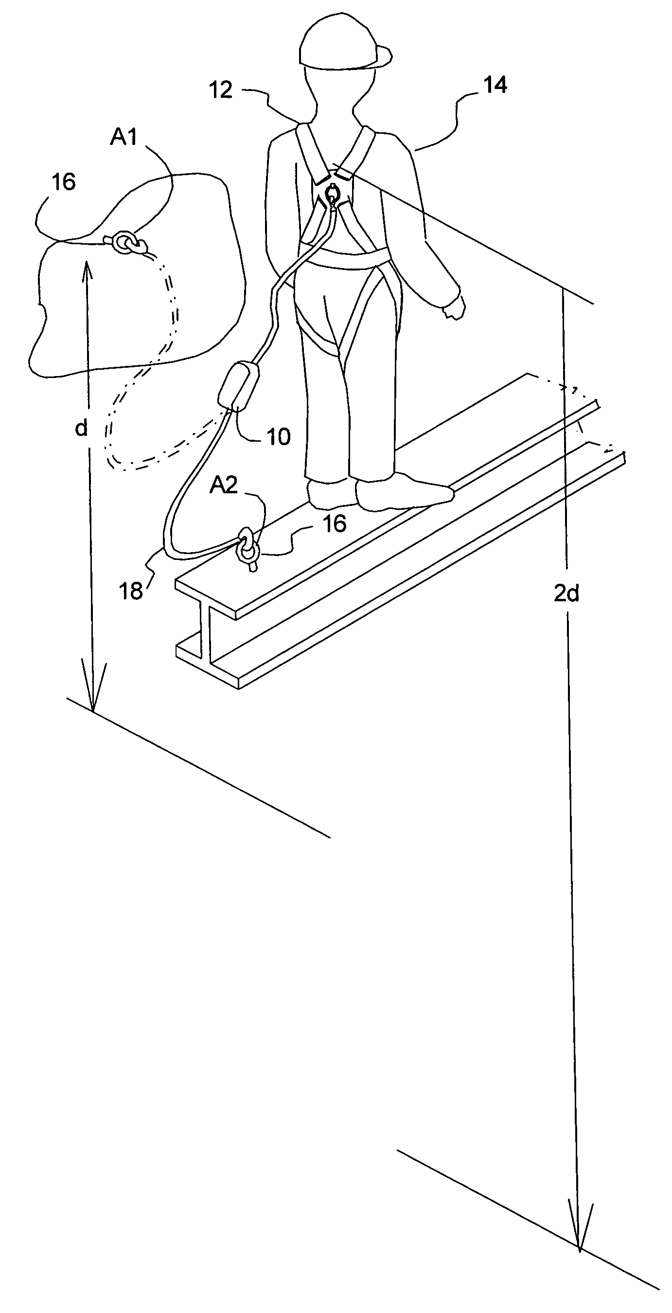
The problem associated with using a shock absorber that provides too small of an arrest force for an extended fall (in this example, greater than six feet) is that the fall will cause the shock absorber to extend fully, until it has reached its full energy capacity and is fully extended.
Such an abrupt stop can expose the worker to force spikes above acceptable levels and result in severe injury to the person relying on the lanyard for safety.
In many applications, there may not be a convenient overhead location where the six-foot long lanyard can be anchored to.
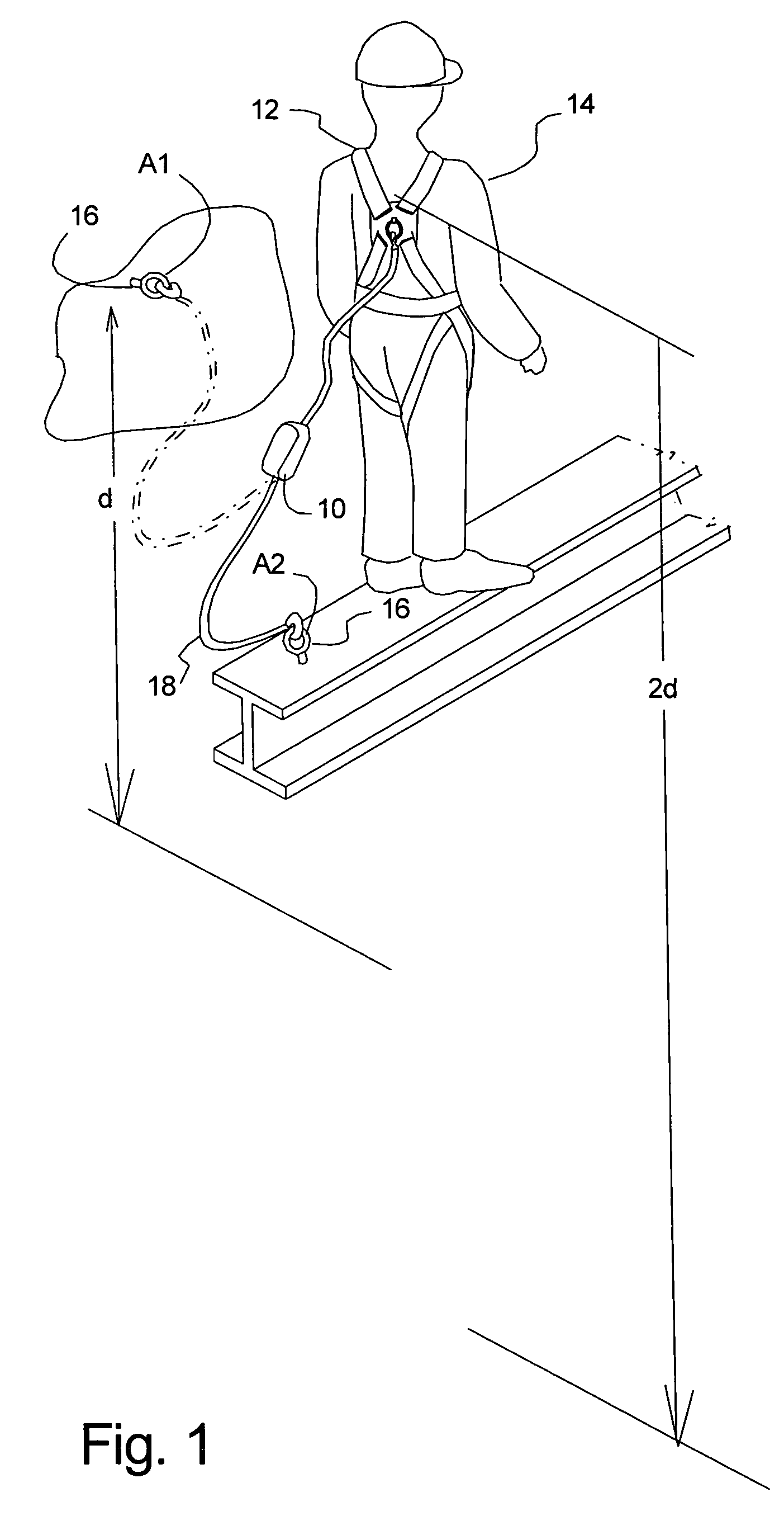
This will result in the exposure of the worker to a 12-foot free fall (the height of the worker plus the length of the lanyard, which is anchored near his feet).
In this situation the use of the six-foot lanyard with the Force level I shock absorber is inadequate.
As stated above, the Force level I shock absorber is designed to protect the

Method used


Image

  • Multiple stage personal fall arrest energy absorber
  • Multiple stage personal fall arrest energy absorber
  • Multiple stage personal fall arrest energy absorber

Examples


Embodiment Construction

[0032]While the invention will be described and disclosed here in connection with certain preferred embodiments, the description is not intended to limit the invention to the specific embodiments shown and described here, but rather the invention is intended to cover all alternative embodiments and modifications that fall within the spirit and scope of the invention as defined by the claims included herein as well as any equivalents of the disclosed and claimed invention.

[0033]Turning now to FIG. 1 where a shock absorber 10 has been illustrated while in use with a safety harness 12 worn by a six-foot tall worker 14. The worker 14 is shown standing on a surface that includes an anchoring point 16 that is at the level of the worker's feet. The anchoring point has been illustrated as being a rigid anchor ring, but may be any anchoring structure or device, examples include structure of the building itself or devices such as clamps, lifelines, and other safety equipment. The shock absorb...


PUM


Abstract

The use of a fall arrest lanyard that provides fall arrest forces at least two primary levels is disclosed. One example provides a lanyard with a pair of shock absorbers of different capacities in series. Other examples use a single shock absorber that provides at least two distinct levels of arrest force. Varying the strength of the attachment area that is to be separated to provide the arrest force and by varying the amount of area being separated at one time varies the levels of arrest force.

Description

BACKGROUND OF THE INVENTION[0001](a) Field of the Invention[0002]This invention generally relates to a device or system for absorbing energy or decelerating an object, such as a falling person. More particularly, but not by way of limitation, to a strap having a connected area designed to tear by breaking the connective threads to create mechanical hysterisis under load and thereby absorb energy.[0003](b) Discussion of Known Art[0004]The use of sewn sections of strap in order to provide a shock absorbing or energy absorbing member for lanyards is well known. See for example U.S. Pat. No. 3,444,957 to Ervin, Jr., incorporated herein by reference. A significant drawback to these devices is that they are often misused by individuals in the field. A common manner in which these devices are misused is by using a device that has been designed for a moderate fall in all situations. For example, a popular version of these shock absorbing lanyards are six-feet in overall length and are desig...

Claims


Application Information

Patent Timeline
IPC IPC(8): A62B35/00
CPCA62B35/04
Inventor CHOATE, GARY E.
Owner RELIANCE INDUSTRIES LIMITED
Why Eureka
Try Eureka