Tracking of a moving object

a technology of moving objects and kinematics, which is applied in the direction of navigation instruments, instruments, and using reradiation, can solve the problems of low estimation accuracy, data delivery, and insufficient results, and achieve the effect of improving the accuracy of estimated kinematics and thereby tracking performan

Active Publication Date: 2008-07-01
SAAB AB
View PDF12 Cites 75 Cited by
  • Summary
  • Abstract
  • Description
  • Claims
  • Application Information

AI Technical Summary

Benefits of technology

[0009]The object of the present invention is to provide a solution for the determination of the kinematics of a moving object, which solution offers a substantial improvement in the accuracy of the estimated kinematics, and thereby in the tracking performance.
[0010]According to one aspect of the invention this object is achieved by the initially described method for determination of the kinematics of a moving object, wherein said kinematic model comprises a guidance law locked on a known position. The method according to the invention enhances the tracking filter performance through the use of a kinematic model comprising a guidance law in the predictive step of the filtering.
[0011]It is assumed that the object navigates according to a set of rules or principles denoted a guidance law. Thanks to the fact that the kinematics of the object is predicted based on an assumption of how the object navigates it is possible to predict the next maneuver of the missile with a high degree of certainty. It is also assumed that the guidance law is locked on a known position, or on an object whose position and velocity is known. This means that it is assumed that the object has an intention to navigate towards the known position. The known position is for example the position of a vehicle or a site, e.g. an aircraft, a boat, or a stationary control station. Those assumptions are essential in the sense that it is this knowledge that makes it possible to predict the motion of the object with much larger certainty, than if the assumption is that the acceleration of the object is zero. Consequently, the process noise for the lateral and vertical axes can be kept much lower than in the general case where there are no apriori knowledge at all on the object maneuvers. This lead to a dramatically lower rate of uncertainty increase for the non-observable states, for example range and closing velocity, during time update.

Problems solved by technology

In such applications, the use of unprocessed sensor data for presentation of information to an operator in a HMI (Human Machine Interface) system, and for further processing, will normally not yield satisfactorily results due to noise artifacts.
Since the warning does not contain any information about the distance to the missile, the distance has to be estimated based on other available data, which leads to low accuracy in the estimation.
A problem with all passive sensors is that they only deliver data in bearing and elevation and cannot measure distance and closing velocity.
This estimation is normally associated with large uncertainties.
Since one normally has no understanding of the next maneuver of the object, the acceleration of the object cannot be predicted.
A draw back with the system and method disclosed in this document is that range and closing velocity of the object is estimated with a bad accuracy, due to the fact that the estimation is based only on previous movements of the object, and no information exists about future maneuvers of the object.

Method used


Image

  • Tracking of a moving object
  • Tracking of a moving object
  • Tracking of a moving object

Examples


Embodiment Construction

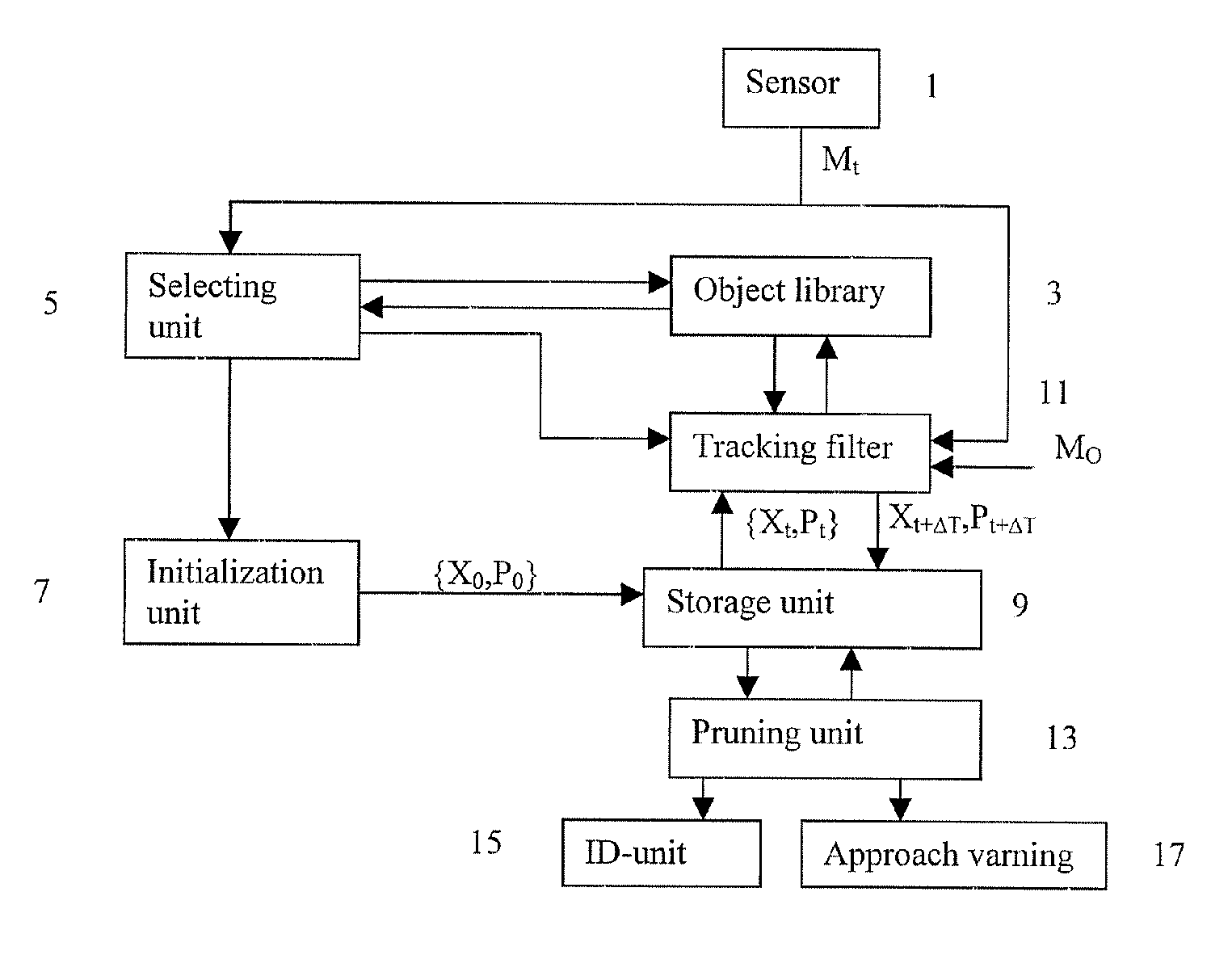
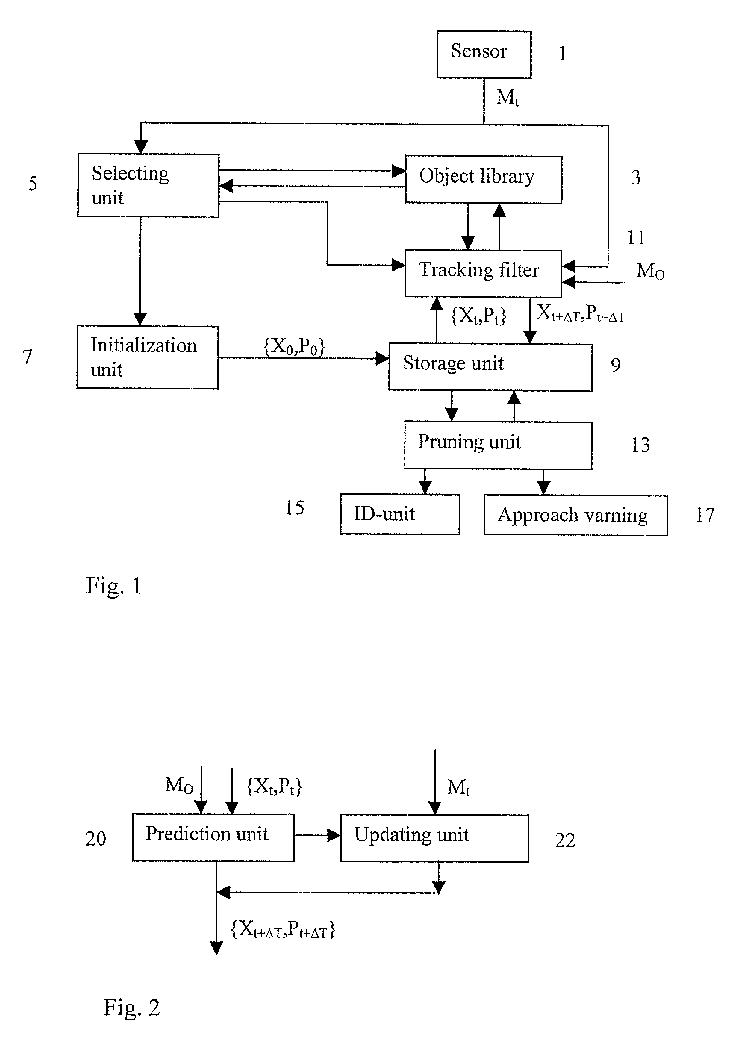
[0034]FIG. 1 shows a block diagram over a system for determining kinematics of a moving object according to an embodiment of the invention. The system comprises at least one sensor 1 capable of producing angle measurements of a moving object. The sensor is preferably arranged on board own ship. Own ship is a vehicle or a site where the system is located. Data received from the sensor comprises at least the horizontal bearing, but it may also comprise the elevation angle. Measurements from additional sensors located on own ship, as well as from external sources, e.g. sensors on other aircraft, boats etc, whose measurements or tracks can be communicated to own ship can also be used to enhance tracking of the object.

[0035]The system comprises an object library 3 adapted for storing guidance laws and object parameters for a plurality of different object types. For each object type parameters such as weight, air resistance, drag resistance and which guidance law the object is assumed to ...


PUM


Abstract

A system for determination of kinematics of a moving object comprising: a sensor producing angular data for the object at a number of observation times, a state initialization unit, receiving angular data from the sensor and on basis thereof determining a first kinematic state of the object, and a tracking filter having a prediction unit, arranged to determine a predicted kinematics state of the object on bases of a kinematic model of the object, wherein the kinematic model comprises a guidance law locked on a known position, and at least one previously determined kinematic state of the object, and a state updating unit, receiving angular data from the sensor and the predicted kinematic state of the object, and on basis thereof determining an updated kinematic state of the object.

Description

FIELD OF THE INVENTION AND PRIOR ART[0001]The present invention relates generally to the improvement of the determination of the kinematics of a moving object. More particularly the invention relates to a method for determination of kinematics of a moving object, and a system for determination of kinematics of a moving object. The invention also relates to a computer program and a computer readable medium.[0002]In many applications, civilian as well as military, there is a desire to be able to estimate the state of a specific process. Typically, these processes are modeled as stochastic processes. The models are then used in conjunction with data from one or more sensors to estimate the state of the process. A general sub-class of these problems is the task of estimating the kinematics of a moving object. Typical applications are air traffic control at airports, and tracking of hostile objects and in numerous military, air, sea, and land applications. In such applications, the use o...

Claims


Application Information

Patent Timeline
Patent Type & Authority Patents(United States)
IPC IPC(8): F41G7/00F41G9/00F42B15/01F42B15/00G01S11/04G01S13/68
CPCG01S11/04
Inventor OLSSON, HAKANWALLENBERG, JANAXELSSON, LEIF
Owner SAAB AB
Why Eureka
Try Eureka