Gradient bore cooling providing RF shield in an MRI system

a gradient coil and imaging system technology, applied in the direction of instruments, magnetic measurements, measurement devices, etc., can solve the problems of reducing the normally reducing the normal attainable signal-to-noise ratio of imaging devices, and reducing the efficiency of imaging devices

Inactive Publication Date: 2008-07-08
GENERAL ELECTRIC CO
View PDF27 Cites 38 Cited by
  • Summary
  • Abstract
  • Description
  • Claims
  • Application Information

AI Technical Summary

Problems solved by technology

The close physical proximity of these different coils results in a significant amount of the energy from the RF excitation field being lost due to impingement upon the gradient field coil structure.
This loss shows up as a damping of the quality factor (Q) of the contained radio frequency coil which, in turn, degrades the normally attainable signal-to-noise ratio of the imaging device.
However, such a solid shield would also seriously attenuate gradient fields extending into the MR magnet bore.
However, this cooling layer takes up space between the RF shield and primary gradient coils.

Method used


Image

  • Gradient bore cooling providing RF shield in an MRI system
  • Gradient bore cooling providing RF shield in an MRI system
  • Gradient bore cooling providing RF shield in an MRI system

Examples


Embodiment Construction

[0024]Reference will now be made in detail to presently preferred embodiments of the present invention. Wherever possible, the same reference numbers will be used throughout the drawings to refer to the same or like parts.

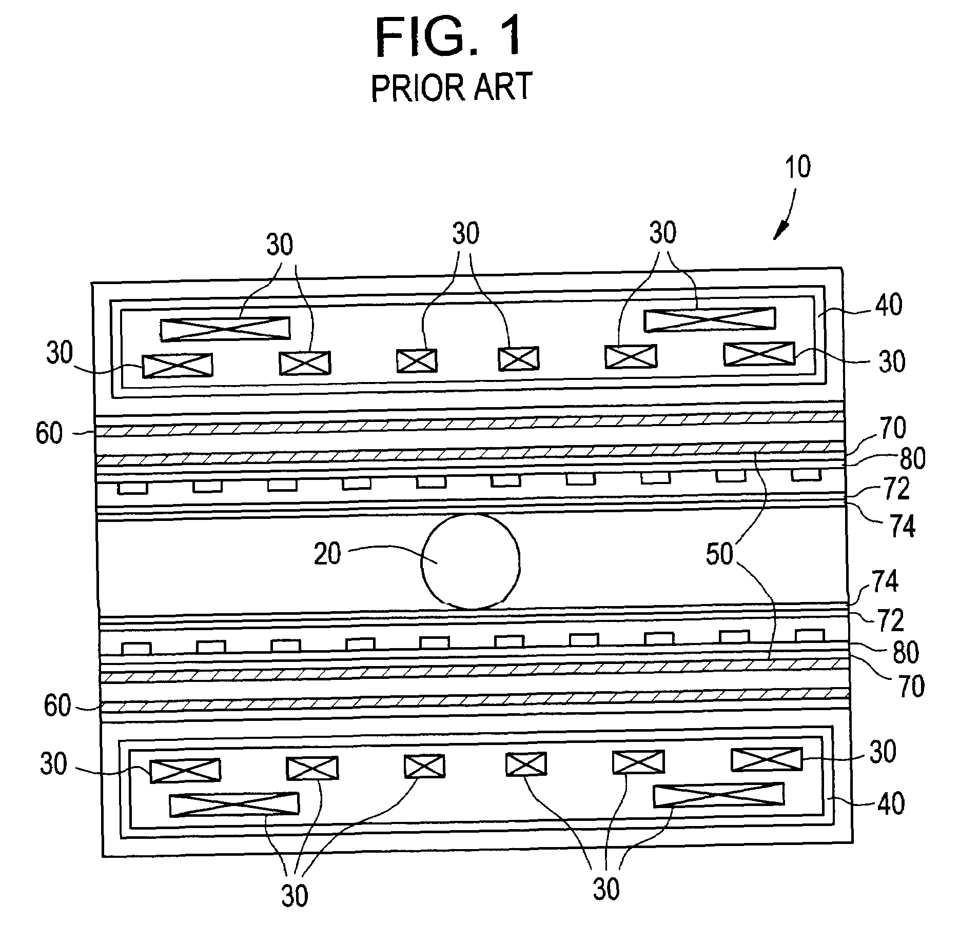
[0025]As shown in FIG. 1, known superconducting (SC) MRI devices 10 typically employ windings 30 for generating a homogeneous magnetic field in an image volume 20, the windings 30 operating in liquid helium to maintain the temperature at approximately 40° K. The liquid helium pool requires a vessel 40 which is vacuum tight and which meets American Society of Mechanical Engineering (ASME) pressure vessel requirements; such a vessel 40 is typically made of welded aluminum alloy cylinders and flanges. Thermal radiation shields (not shown), of which two are typically used, are also made of welded aluminum pieces and contain the helium vessel 40.

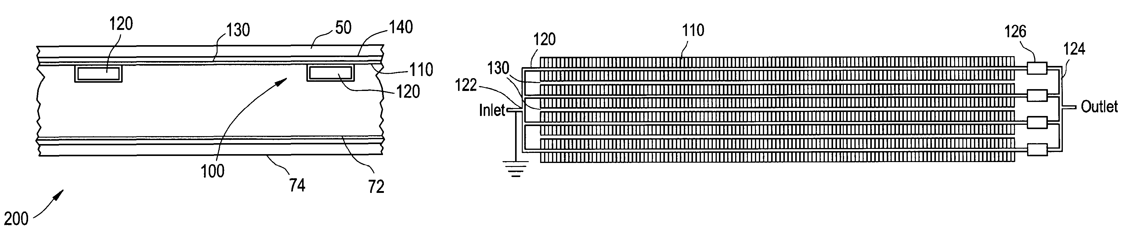
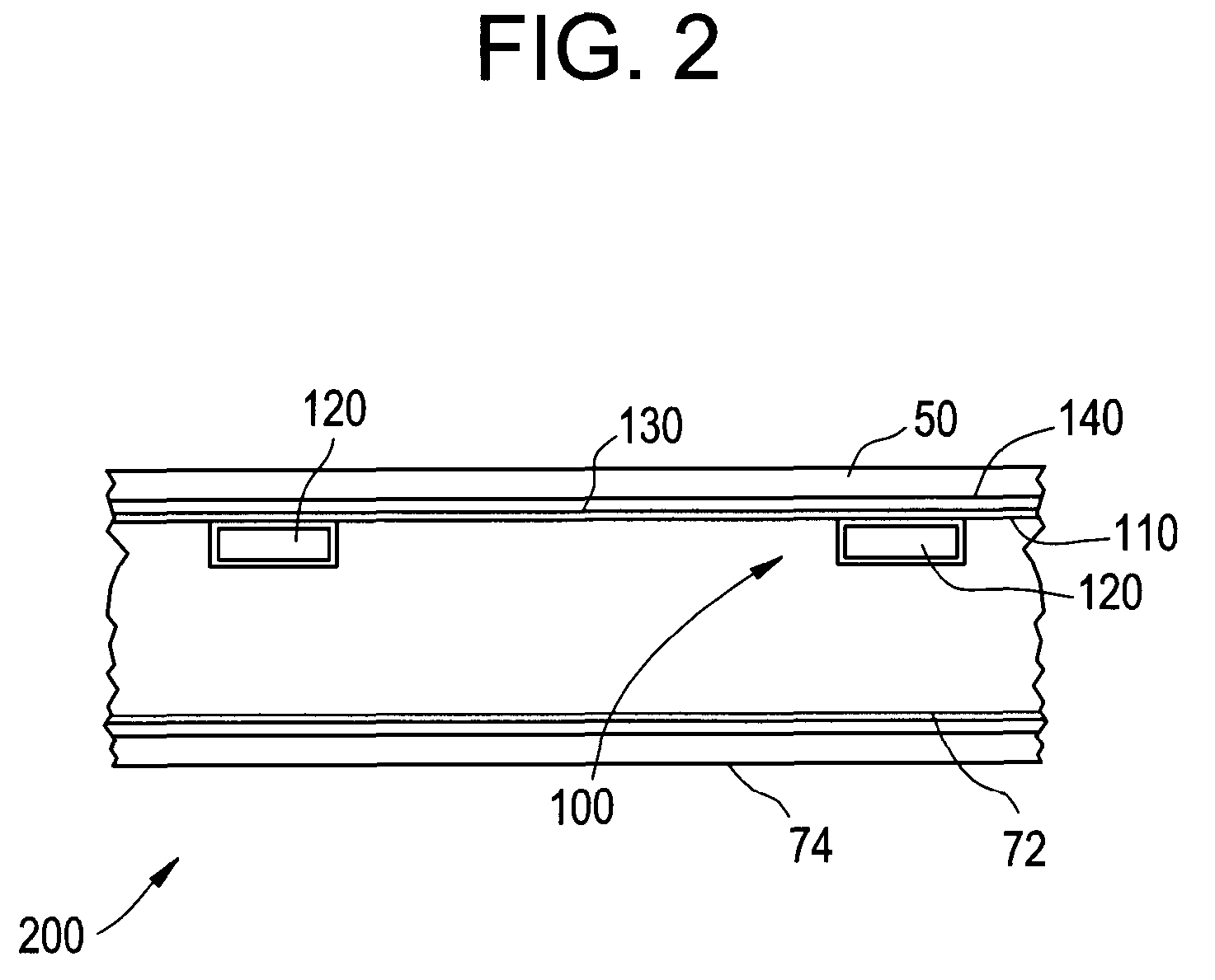
[0026]When the gradient coils 50 in the bore of the MRI device 10 are electrically pulsed, the resulting time changing magneti...


PUM


Abstract

A magnetic resonance imaging (MRI) device for imaging a volume includes a main magnet for generating a magnetic field, an insulator sheet formed into a tube extending along an axis, a gradient coil disposed on an outside surface defining the tube for manipulating the magnetic field generated by the main magnet to image the volume, and a cooling circuit disposed between the gradient coil and a RF coil. The cooling circuit is disposed on an opposite inside surface defining the tube, wherein the cooling circuit shields the gradient coil from the RF coil while cooling the gradient coil.

Description

BACKGROUND OF THE INVENTION[0001]This application claims the benefit of a priority under 35 U.S.C. 119 to Great Britain Patent Application No. 0423325.0 filed Oct. 20, 2004, the entire contents of which are hereby incorporated by reference.[0002]This invention generally relates to a radio frequency (RF) and gradient coil arrangement for a magnetic resonance (MR) imaging system or scanner. More particularly, the invention pertains to an arrangement wherein the RF coil of the MR scanner is selectively mounted in relation to other components of the scanner, to substantially increase RF coil performance, by maximizing separation therebetween while sufficiently cooling the gradient primary coil.[0003]As is well known, a MR imaging system or scanner commonly includes a cryostat, which contains a powerful superconductive main magnet positioned around a main magnet bore. The superconductive magnet is maintained at an extremely cold temperature and produces a strong static magnetic field, or...

Claims


Application Information

Patent Timeline
Patent Type & Authority Patents(United States)
IPC IPC(8): G01V3/00G01R33/34G01R33/385G01R33/422
CPCG01R33/422G01R33/3856G01R33/34046
Inventor CIREL, CHRISTOPHER MARK
Owner GENERAL ELECTRIC CO
Why Eureka
Try Eureka