

Leaf, multi-leaf collimator, device for delimiting beams and irradiation device
a collimator and multi-leaf technology, applied in the field of leaves for multi-leaf collimators, can solve the problems of large specific weight, complicating the handling of collimators on irradiation devices, price and delivery times, etc., and achieve the effect of reducing weigh
- Summary
- Abstract
- Description
- Claims
- Application Information
AI Technical Summary
Benefits of technology
Problems solved by technology
Method used
Image

Examples
first embodiment
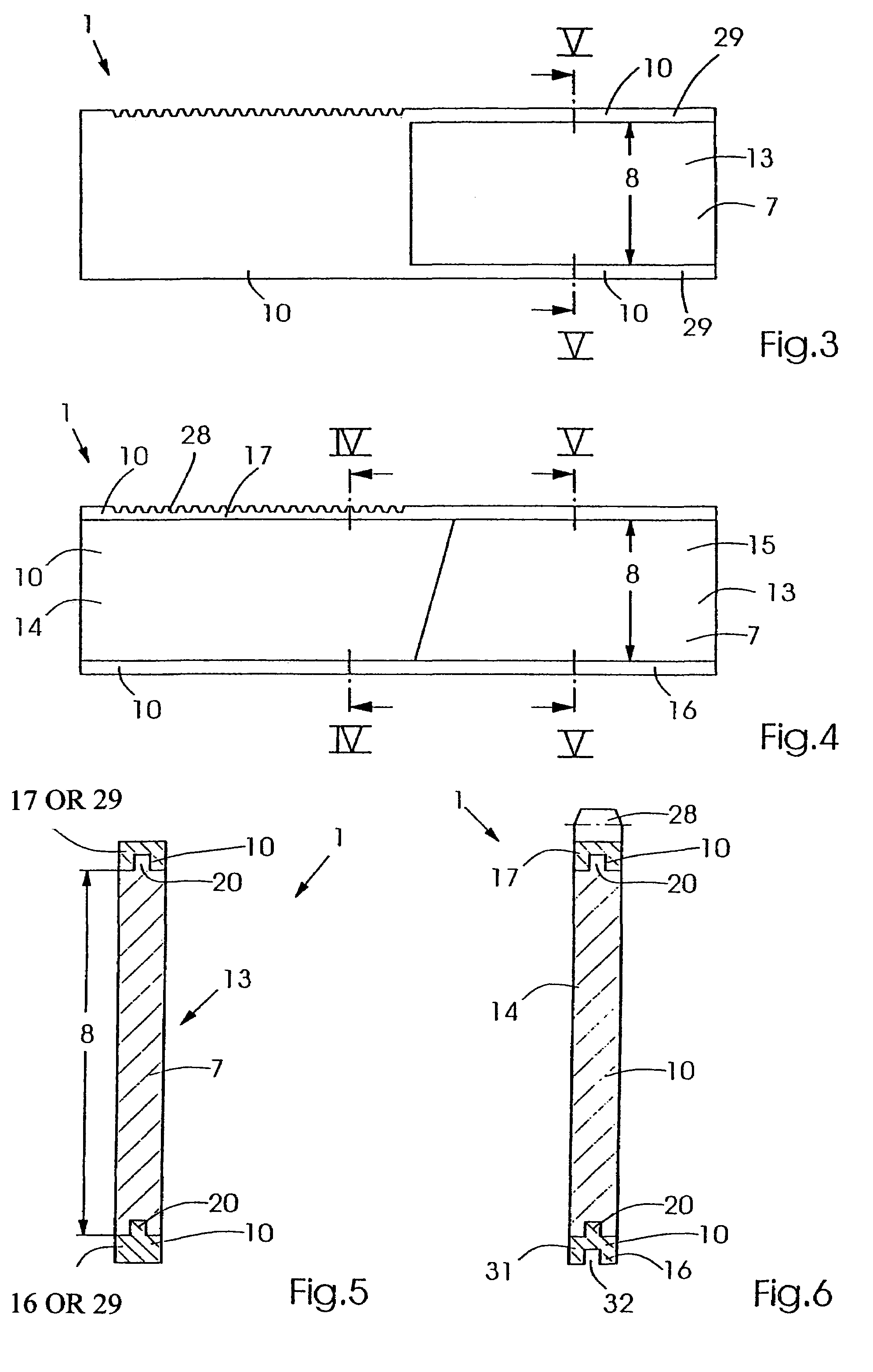
[0042]FIG. 3 shows a leaf 1. The design provides that the other material 10 has two holding bars 29 towards the front, which form a recess 13 in which the radiation-absorbing material7 is inserted. It must, of course, have the full thickness 8 which is required for absorption of the beams 3. This increases the stability and provides good seating of the beam-absorbing material 7. FIG. 5 shows a sectional view V-V.
second embodiment
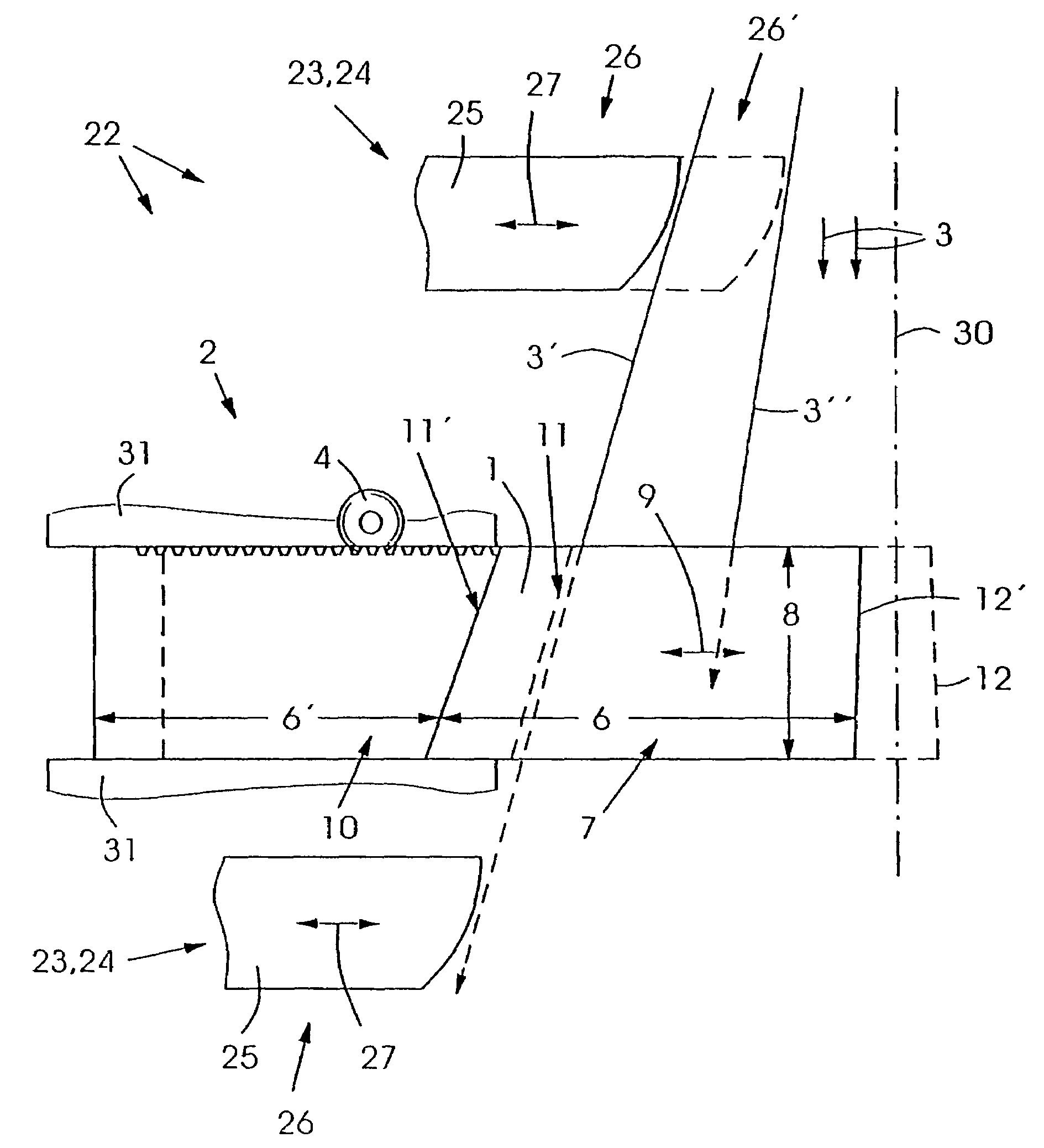
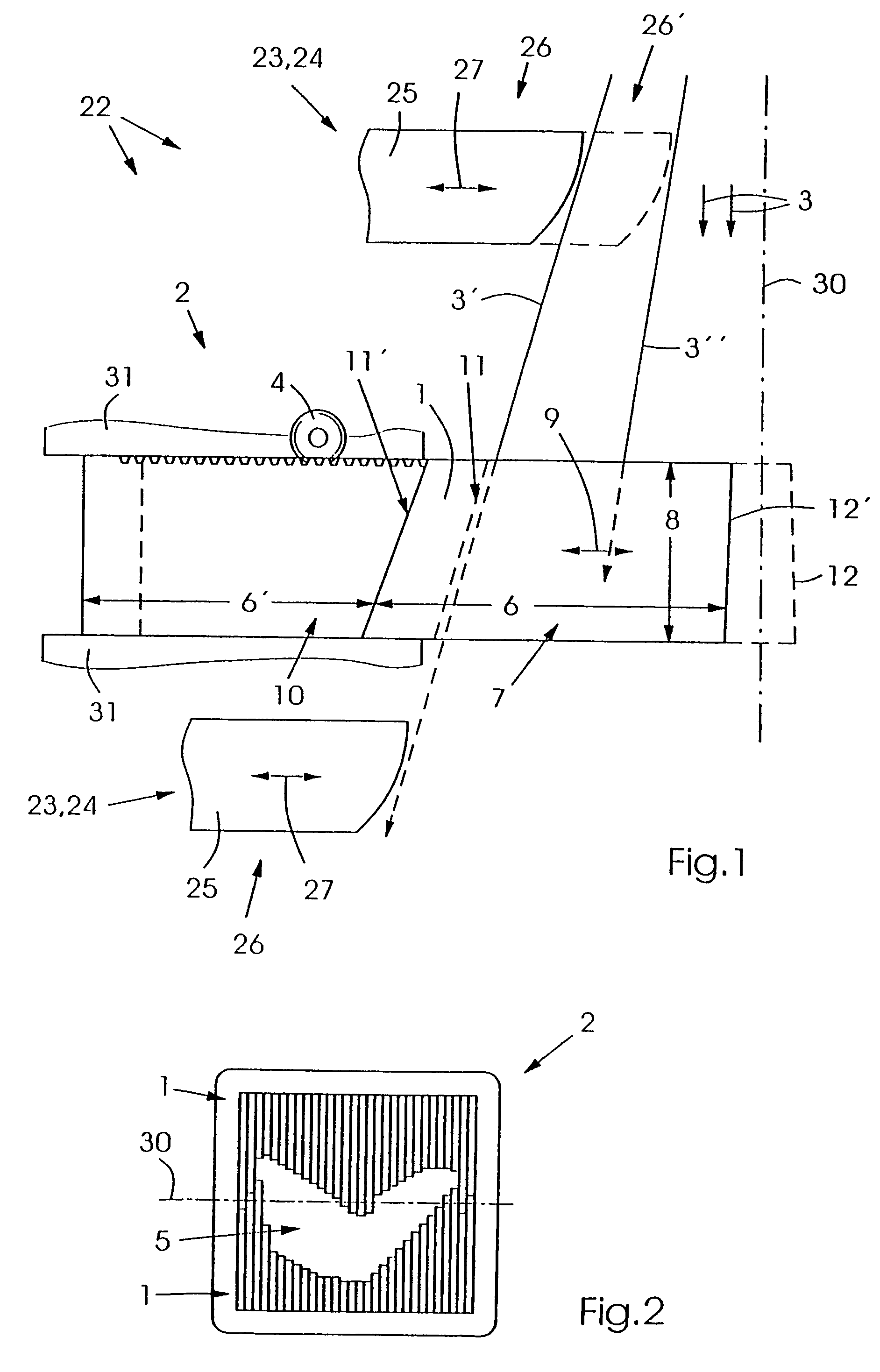
[0043]FIG. 4 shows a leaf 1. It consists of a rear part 14 and a front part 15, wherein the rear part 14 consists of the other material 10, e.g. steel, and the front part 15 consists of the beam-absorbing material 7, e.g. of tungsten. These two parts 14 and 15 are located between two narrow, elongated parts 16 and 17, wherein 16 is a guiding part and 17 is a driving part. The driving part 17 may e.g. be a toothed rack 28 and the guiding part 16 a guide 31 comprising guiding groove 32 which runs in a rail of complementary design. The latter is shown in FIG. 6, as is the design of the driving part 17 as a toothed rack 28.
[0044]FIG. 5 shows a section V-V which may be identical to FIG. 3 and FIG. 4. The upper and lower sides of the beam-absorbing material 7 may be provided with a guiding part 16 and a driving part 17 or with one holding bar 29 each. For secure and accurate connection, a tongue and groove joint 20 may be provided while ensuring that the thickness 8 of the beam-absorbing ...
third embodiment
[0046]FIG. 7 shows a leaf 1 which comprises a joint 11 of angular design to increase stability and provide exact seating. The region of the leaf 1 which consists of the other material 10, e.g. steel has openings 21 to further reduce weight. FIG. 7 may also represent a block 18 since it is designed in an identical manner to the leaves 1, but has multiple times the width 19 such that the individual leaves 1 can be cut therefrom.
[0047]FIG. 8 shows such a block, wherein identical reference numerals represent the above-mentioned parts. It shows that all above-mentioned designs may already be provided such that the leaves 1 shown in FIG. 7 can be produced after cutting the block 18.
[0048]The drawing shows, of course, only a selection of possible features of the inventive items. They can be combined in any arbitrary manner. Each inventive leaf 1 may e.g. comprise recesses 21. The leaves 1 may also be designed in another manner, e.g. have front edge adjustment or another design for joining ...
PUM
 Abstract
Description
Claims
Application Information