Method and apparatus for monitoring a passageway using 3D images

Inactive Publication Date: 2008-07-08
COGNEX TECH & INVESTMENT
View PDF57 Cites 30 Cited by
  • Summary
  • Abstract
  • Description
  • Claims
  • Application Information

AI Technical Summary

Benefits of technology

[0016]The present invention also features trajectory based triggering whereby SDS is able to segment objects in 3D space and track them using a custom algorithm, such as Patquick available from Cognex Corp. of Natick, Mass., which is far superior to tracking their projections in 2D image space using standard block matching methods.
[0017]The present invention also features calibrated 3D system whereby SDS is calibrated in real world units. The invention is thereby it is able to accept setup parameters and triggers based on real world heights and distances.
[0018]The present invention also features optional storage of stereoscopic images for a predefined time interval. This option can provides video evidence in presence of a mishap or can be used to reconstruct a full 3D scene over an extended period. Such extended data can provide a more o

Problems solved by technology

Such sensors are not well suited for certain security systems because they are easily circumvented; they only detect a certain class of objects moving through a narrowly constrained space; and they can not directly determine an object direction or velocity.
These sensors often have problems maintaining uniform sensitivity throughout a monitored space or over time and can be prohibitively expensive.
These systems can be too

Method used


Image

  • Method and apparatus for monitoring a passageway using 3D images
  • Method and apparatus for monitoring a passageway using 3D images
  • Method and apparatus for monitoring a passageway using 3D images

Examples


Embodiment Construction

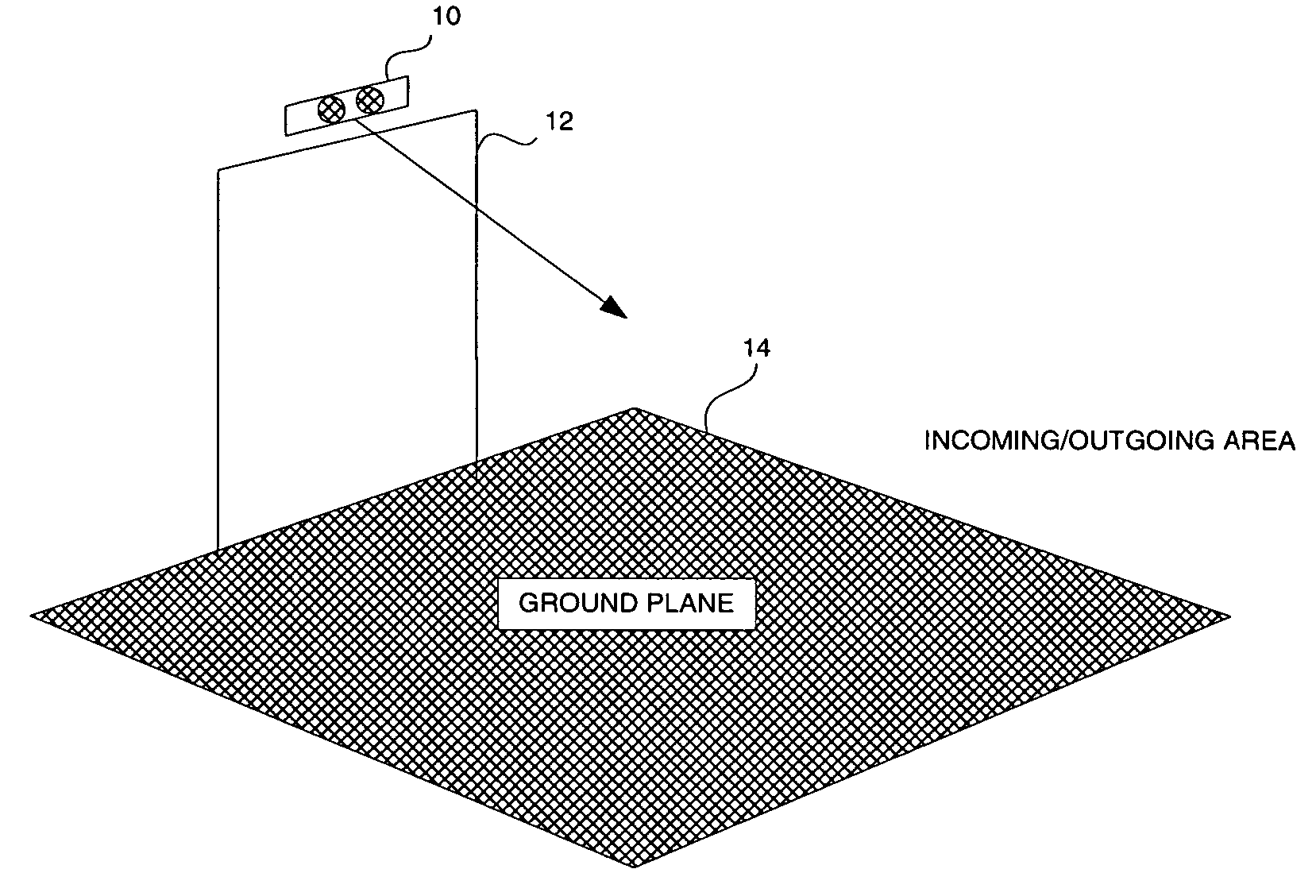
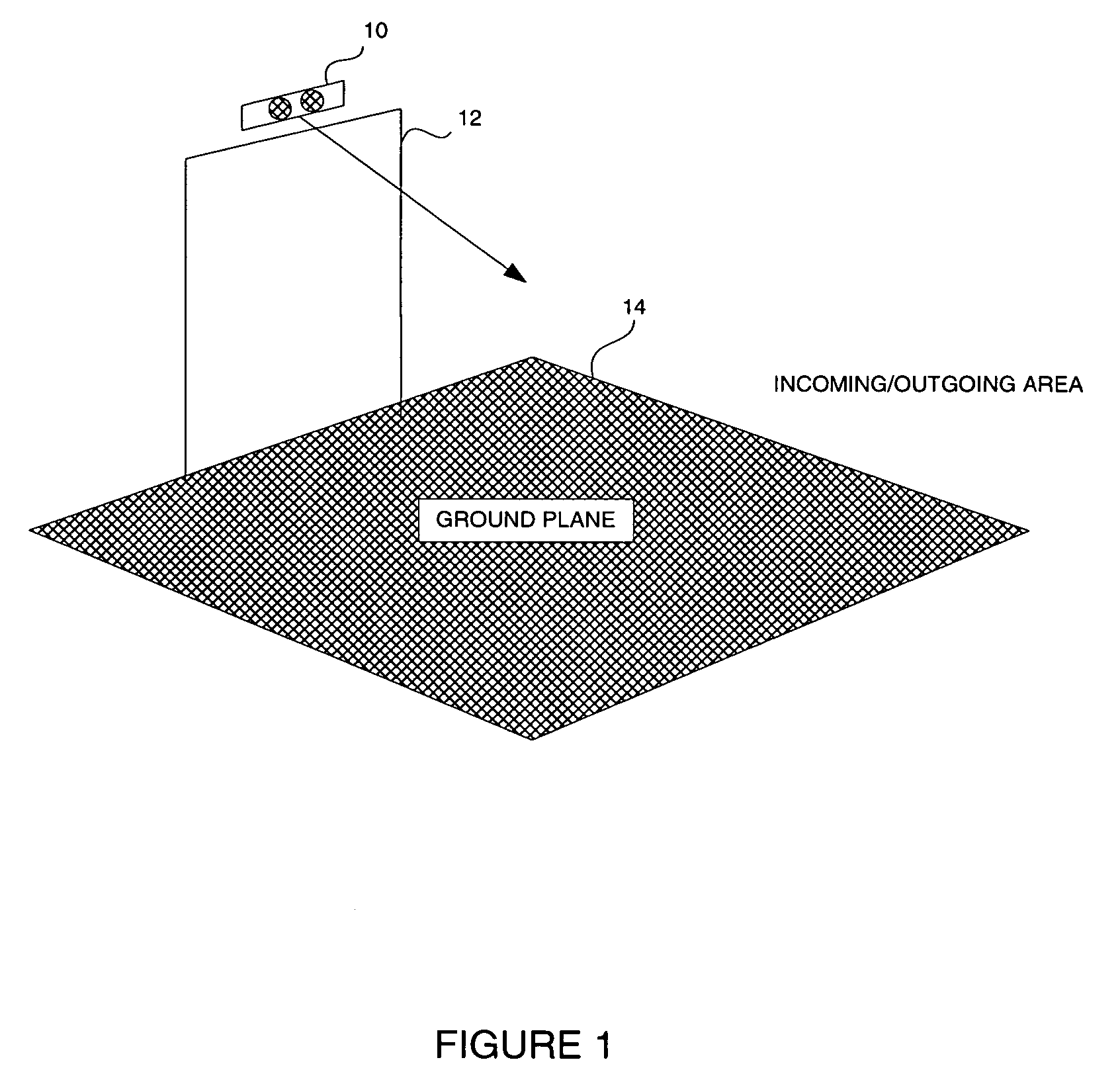
[0027]The layout of an illustrative embodiment of the present invention is described with the reference to FIG. 1. The illustrative embodiment includes a set of stereo cameras 10 mounted above a passageway 12 looking downward and outward towards the incoming area 14. Optionally, another set of cameras (not shown) can be mounted on the other side of the passageway looking at the outgoing area. The invention is calibrated to provide heights above the ground plane for any point in the field of view. Therefore, when any object enters the field of view, it generates interest points called “features,” the heights of which are measured relative to the ground plane. These points are then clustered in 3D space to provide “objects.” These objects are then tracked in multiple frames to provide “trajectories.” Such a system could then trigger an event such as an alarm or open or close a gate, for example, based on the various pieces of information generated about the object.

[0028]In the illustr...


PUM


Abstract

A stereo imaging based vision system is calibrated to provide heights above the ground plane for any point in the field of view. Therefore, when any object enters the field of view, it generates interest points called “features,” the heights of which are measured relative to the ground plane. These points are then clustered in 3D space to provide “objects.” These objects are then tracked in multiple frames to provide “trajectories.” Such a system could then control alarm signals or actuate gates or motion control devices, for example, based on the various pieces of information generated about the object.

Description

CROSS REFERENCE TO RELATED APPLICATIONS[0001]The present application is a continuation in part of U.S. application Ser. No. 10 / 388,925 filed Mar. 14, 2003 which claims benefit of Provisional Application 60 / 408,266 filed Sep. 5, 2002.FIELD OF THE INVENTION[0002]The present invention relates to machine vision systems and more particularly to a method and apparatus using machine vision to detect objects moving in a particular direction in an area and cause an automated response thereto.BACKGROUND OF THE INVENTION[0003]The movement of people or objects through various spaces and passageways must be monitored or controlled for any number of purposes including safety and security purposes. Such monitoring and control are performed most efficiently when it is done automatically by machine with little or no human interventions.[0004]Various sensors are known for use in automatic object detection systems. For example, photo voltaic sensors detect objects interrupting a beam of visible or UV ...

Claims


Application Information

Patent Timeline
IPC IPC(8): G06K9/00E05F15/20G01V8/10G06T1/00G06T7/00G06T7/20
CPCG01V8/10G06K9/00771E05F15/73G06T7/2086E05F2015/767G06T2207/30241G06T7/285G06V20/52
Inventor NICHANI, SANJAYSCHATZ, DAVID
Owner COGNEX TECH & INVESTMENT
Why Eureka
Try Eureka