Method and apparatus for the measurement of the acoustic impedance

a technology of acoustic impedance and measurement method, which is applied in the direction of volume measurement apparatus/method, liquid/fluent solid measurement, sensor, etc., can solve the problems of no longer usable methods, geometric problems, and disadvantages of both methods, and achieve the effect of easy and simple measurement of impedances

Inactive Publication Date: 2008-07-08
SONOVA AG
View PDF9 Cites 9 Cited by
  • Summary
  • Abstract
  • Description
  • Claims
  • Application Information

AI Technical Summary

Benefits of technology

[0011]An object of the present invention is to provide a measuring method for an easy and simple measurement of impedances by overruling the known disadvantages. A further object is to provide an apparatus for performing such measurements.SUMMARY OF THE INVENTION
[0023]In a further embodiment, an acoustic resistor will be arranged between the stimulation and the microphone. It has been shown that the accuracy of the measurement will thus be further enhanced. The resistor may be optimized in view of-the sensitivity due to microphone errors.
[0026]The need of flexibility with respect to the coupling in the field of ear impedance measurement will be advantageously accomplished by the present invention, which allows the measurement with individual adaptors which are quickly built and calibrated.

Problems solved by technology

But both of the described methods suffer of some disadvantages.
Furthermore, those methods are no longer usable if the stimulation changes between calibration and measurement, i.e. if the voltage of the generator is not constant.
After all, noise effects occurring during the active measurement of the voltage over the second impedance will falsify the result.
The universal application of the measurement method according to U.S. Pat. No. 4,289,143 for the measuring of general acoustic impedances will as well lead to geometrical problems.
As all three connectors for loudspeaker, microphone and static pressure generator are arranged in the same plane at the exit of the probe, in which plane the impedance to be measured is defined, the coupling of individual acoustic elements will lead to geometrical problems, especially if the opening cross section is smaller than the diameter of the probe.
The use of complex modules such as wind shields or membranes is as well problematic.
Furthermore in the field of ear measurement, the risk of choking the probe occurs, which rules out the measurement or destroys the calibration and therefore falsifies the result.

Method used


Image

  • Method and apparatus for the measurement of the acoustic impedance
  • Method and apparatus for the measurement of the acoustic impedance
  • Method and apparatus for the measurement of the acoustic impedance

Examples


Embodiment Construction

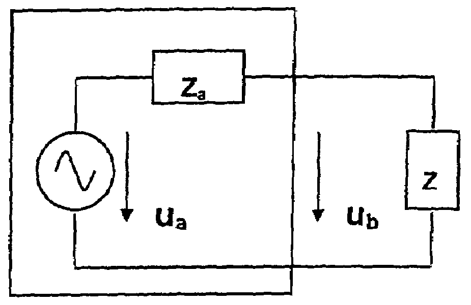
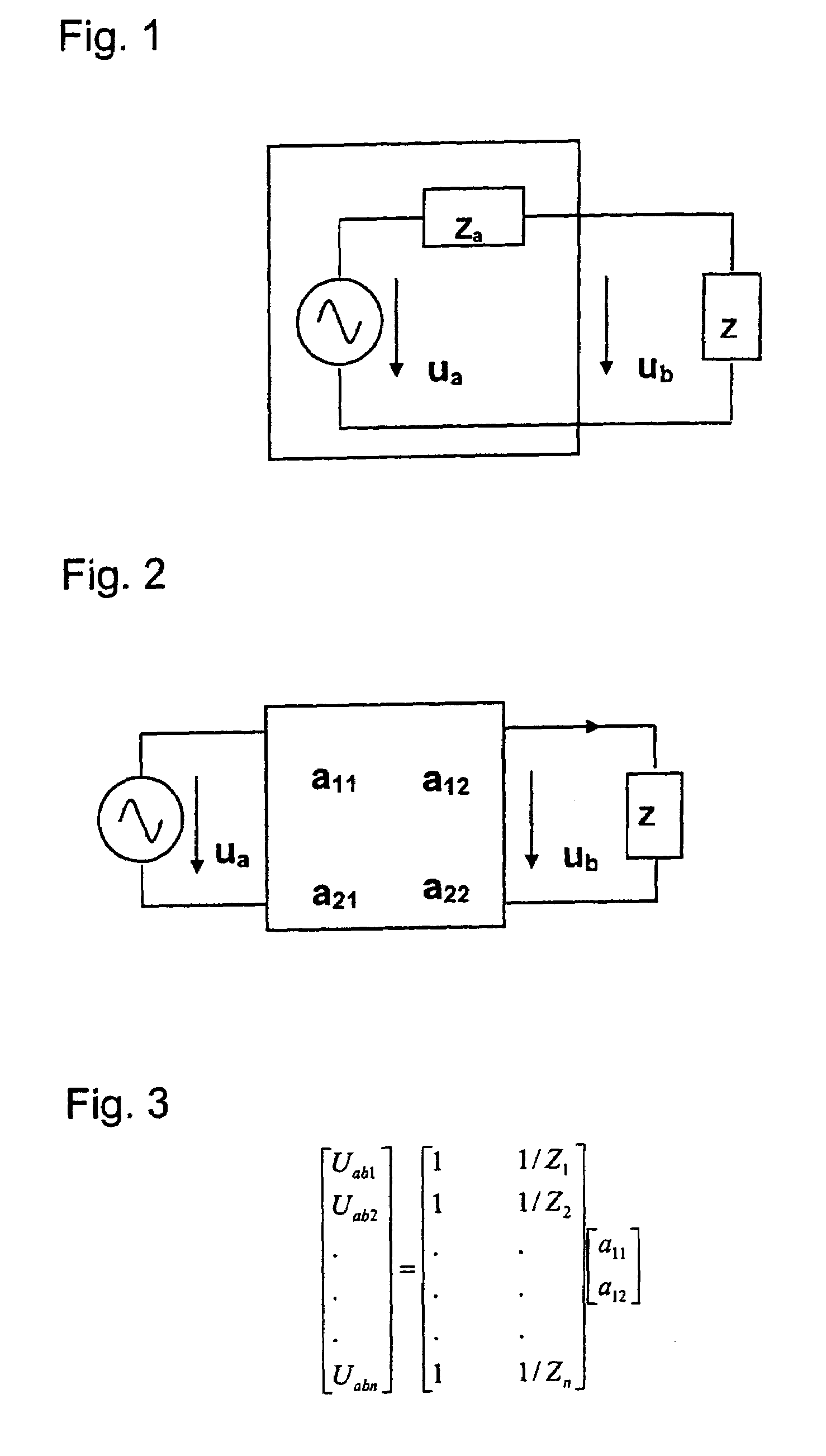
[0034]FIG. 1 shows schematically the principle of a measurement of an unknown impedance according Thévenin. This principle is based on a base system, which is theoretically described as a voltage source with the complex voltage ua and a total serial impedance Za. This base system serves for the stimulation and transforming of the voltage to the impedance Z to be measured. A voltage ub may be measured over this load impedance Z. The values stand thereby in the following relation:

[0035]Z=ubZaua-ub

[0036]The parameters ua und Za may be calculated by performing measurements with at least two known calibration impedances Z(1) and Z(2). The load impedance Z can thus be determined by the measuring of the voltage ub according the above equation. It has to be considered that all magnitudes or values respectively are complex functions in relation to the frequency of the stimulation voltage ua. That is the reason why the phase relation between ua und ub has to be known, which phase relation has...


PUM


Abstract

A probe located in an area to be measured has an acoustic stimulator, (e.g., a loudspeaker and a microphone). The stimulator sends acoustic signals to the microphone where the signals are transformed into electrical signals and transferred to an analysis unit. Using a defined stimulation followed by a two-port chain transfer matrix connected to an impedance as a model, the voltage ratio between the stimulation and the impedance is described as a dimensionless transfer function of a complex function of the stimulation frequency. A series of acoustic calibration signals are generated by known acoustic impedances covering different calibration scopes using the stimulation. The calibration signals are recorded and the electric values are merged with the respective voltage values of the stimulation for evaluation of the respective transfer functions which are merged together into an over-determined linear system of equations. The impedance is determined by evaluating the transfer functions.

Description

FIELD OF THE INVENTION[0001]The present invention relates to a method and an apparatus for the determination of the acoustic impedance, and more particularly to the determination of the acoustic impedance of cavities such as the human ear.BACKGROUND OF THE INVENTION[0002]A measurement system consisting of two components will conventionally be used for the determination of the acoustic impedance of a closed room. The two components are a microphone and a loudspeaker which are connected to an analysis unit. This arrangement is frequently supplemented by a third connector to apply static pressure.[0003]A probe with three connectors is especially used for the measurement of the acoustic impedance of the ear in functional relationship to the static pressure for diagnostic purposes. The connectors thereby couple the probe, which is inserted into the ear channel, with a static pressure generator, a microphone and a loudspeaker.[0004]The evaluation of the measurement will thereby be perform...

Claims


Application Information

Patent Timeline
Patent Type & Authority Patents(United States)
IPC IPC(8): G01F17/00G01H15/00
CPCG01H15/00
Inventor STIRNEMANN, ALFRED
Owner SONOVA AG
Why Eureka
Try Eureka