Pump unit with multiple operation modes

a pump unit and operation mode technology, applied in the field of pump units, can solve the problems of increased cost, increased discharge pressure, excessive noise and vibration of the pump unit, etc., and achieve the effects of reducing noise and vibration, high discharge pressure, and high flow rate operations

Active Publication Date: 2008-07-15
DAIKIN IND LTD
View PDF14 Cites 13 Cited by
  • Summary
  • Abstract
  • Description
  • Claims
  • Application Information

AI Technical Summary

Benefits of technology

[0005]Accordingly, an object of the present invention is to provide a pump unit capable of obtaining a high discharge pressure with use of a relatively small-torque motor, and yet capable of reducing noise and vibrations, during high flow-rate operations.
[0019]Further, in the first and second modes, since the variable-speed motor is controlled by the control device so that a constant-horsepower operation is performed, discharge pressure and flow rate are autonomously controlled without receiving any command signal from external of the pump unit. Therefore, input signal lines for commands can be omitted, allowing the wiring to be simplified, and moreover operations for inputs of the command signals become unnecessary, thus making the pump unit easier to operate.
[0021]According to the pump unit of the above-mentioned embodiment, the switching valve is switched over from connecting state to disconnecting state based on the rotational speed of the variable-speed motor, while the switching valve is switched over from disconnecting state to connecting state based on the detected pressure by the pressure sensor. Therefore, since the dead band of control inevitably becomes larger in width, it can be prevented that the switching valve becomes unstable between connecting state and disconnecting state. As a result, hunting of pressure and flow rate of the discharge fluid of the pump unit can be prevented.
[0022]Further, since a constant-horsepower operation is performed by the control device, and since the switching valve is switched over based on the rotational speed of the motor and the detected value of the pressure sensor, the control of discharge pressure and flow rate as well as the switching of operational mode are autonomously controlled without receiving any command signal from external of the pump unit. Therefore, input signal lines for commands can be omitted, allowing the wiring to be simplified, and moreover operations for inputs of the command signals become unnecessary, thus making the pump unit easier to operate.
[0024]According to the pump unit of the above-mentioned embodiment, the switching valve is switched over from disconnecting state to connecting state based on the rotational speed of the variable-speed motor, while the switching valve is switched over from connecting state to disconnecting state based on the detected pressure by the pressure sensor. Therefore, since the dead band of control inevitably becomes larger in width, it can be prevented that the switching valve becomes unstable between connecting state and disconnecting state. As a result, hunting of pressure and flow rate of the discharge fluid of the pump unit can be prevented.
[0025]Further, since a constant-horsepower operation is performed by the control device, and since the switching valve is switched over based on the rotational speed of the motor and the detected value of the pressure sensor, the control of discharge pressure and flow rate as well as the switching of operational mode are autonomously controlled without receiving any command signal from external of the pump unit. Therefore, input signal lines for commands can be omitted, allowing the wiring to be simplified, and moreover operations for inputs of the command signals become unnecessary, thus making the pump unit easier to operate.

Problems solved by technology

Using the large-torque motor would cause a problem of an upsizing of the pump unit as well as an increase in cost.
Also, using the small- and fixed-capacity type pump would cause the rotational speeds of the pump and the motor to become excessively large ones during high flow-rate operations, posing a problem of excessively large noise and vibrations of the pump unit.

Method used


Image

  • Pump unit with multiple operation modes
  • Pump unit with multiple operation modes
  • Pump unit with multiple operation modes

Examples


Embodiment Construction

[0032]Hereinbelow, the present invention is described in detail by embodiments thereof illustrated in the accompanying drawings.

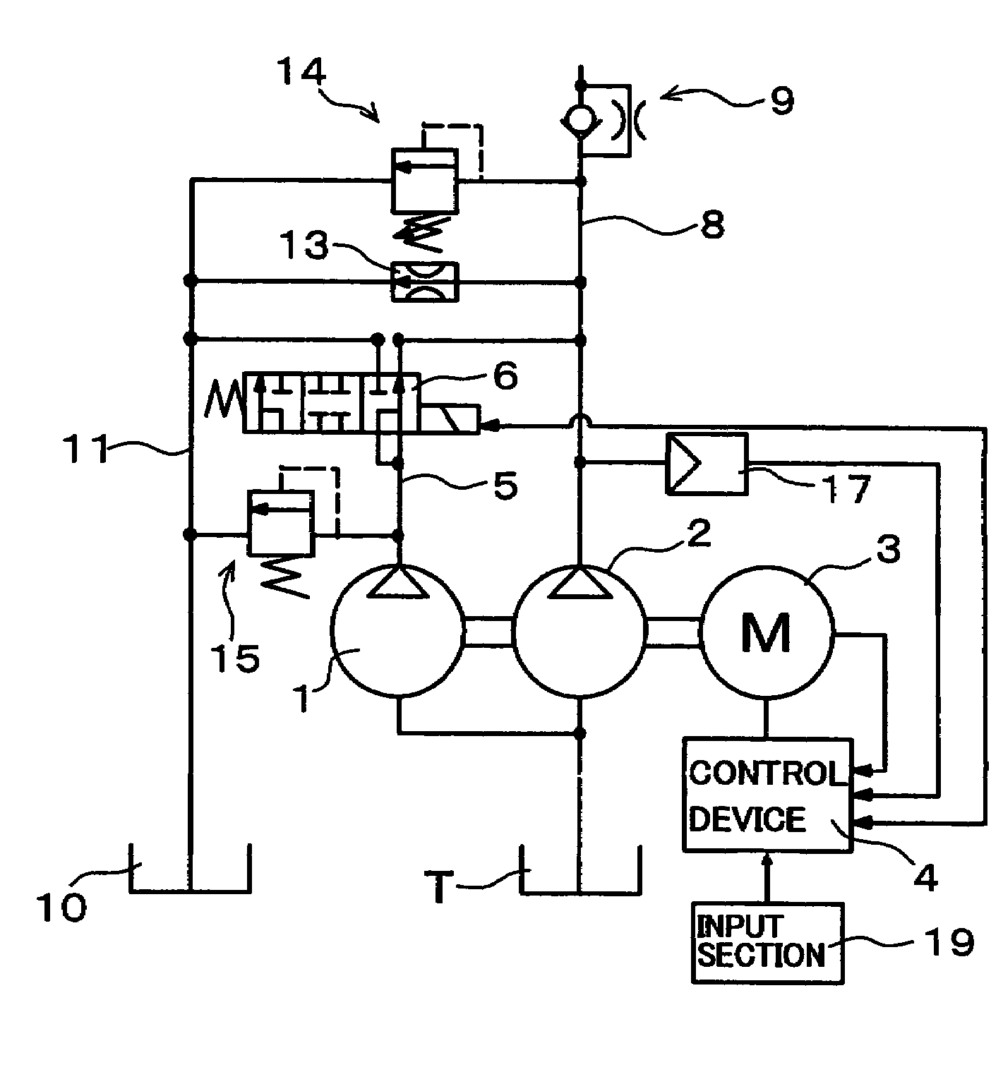
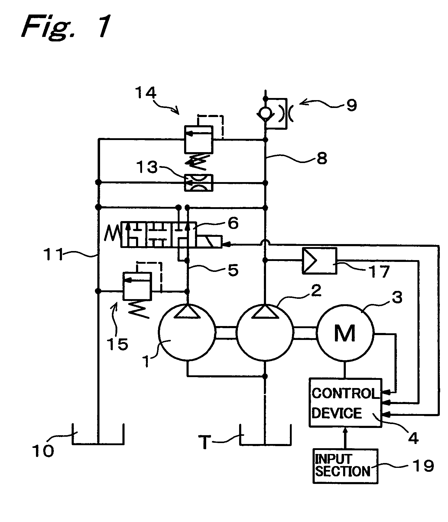
[0033]FIG. 1 is a view showing a pump unit of an embodiment of the present invention. This pump unit is a pump unit that feeds a working fluid of a tank T to an unshown actuator such as hydraulic cylinder. This pump unit has a first pump 1 as a first fixed-capacity type pump of large capacity, and a second pump 2 as a second fixed-capacity type pump of small capacity directly connected to the first pump 1. The first pump 1 is a gear pump of 5.5 cc / rev., and the second pump 2 is a gear pump of 3.5 cc / rev. These first pump 1 and second pump 2 are connected to a variable-speed motor 3, and this variable-speed motor 3 is electrically connected to a control device 4. An outlet port of the first pump 1 is connected to a first discharge line 5, and an outlet port of the second pump 2 is connected to a second discharge line 8. The first discharge line 5 is connecte...


PUM


Abstract

A first pump of small capacity and a second pump of large capacity are connected directly with each other and are driven by a variable-speed motor. The rotational speed of the variable-speed motor is controlled by a control device. In a first mode, a first discharge line of the first pump and a second discharge line of the second pump are disconnected with each other, making the first pump unloaded. With the first pump in the unloaded state, a constant-horsepower operation is performed, where the discharge fluid is brought into a high pressure by relatively small torque. In a second mode, the first discharge line and the second discharge line are connected with each other by a switching valve. With the first and second discharge lines in the connected state, a constant-horsepower operation is performed, where a high flow rate of discharge fluid is discharged at relatively low rotational speed.

Description

TECHNICAL FIELD[0001]The present invention relates to a pump unit.CROSS-REFERENCE TO RELATED APPLICATIONS[0002]This nonprovisional application claims priority under 35 U.S.C. §119(a) to Japanese Patent Application No. P2002-169554 filed in Japan on Jun. 11, 2002, the entire contents of which are hereby incorporated by reference.BACKGROUND ART[0003]Conventionally, there has been provided a pump unit shown in FIG. 4. This pump unit has a fixed-capacity type pump 52 whose rotational speed is variably driven by a variable-speed motor 51, and a controller 53 for controlling the rotational speed of the variable-speed motor 51 by changing the frequency of supply current to the motor 51. This controller 53, upon receiving a signal from a pressure sensor 54 which detects a pressure of a discharge line of the pump 52, controls the rotational speed of the variable-speed motor 51 so that the value of the pressure detected by the pressure sensor 54 becomes a specified value, thus controlling the...

Claims


Application Information

Patent Timeline
Patent Type & Authority Patents(United States)
IPC IPC(8): F04B49/06F04B49/00F04B49/08F04C14/02F04C14/06F04C14/08
CPCF04B49/002F04B49/007F04B49/06F04B49/065F04C14/02F04C14/06F04C14/08F04B49/08F04C2270/56
Inventor HORIUCHI, HITOSHIOCHI, YOSHIYUKINAKATSUJI, JUN
Owner DAIKIN IND LTD
Why Eureka
Try Eureka