Jet velocity vector profile measurement and control

a jet velocity vector and profile technology, applied in the field of papermaking, can solve the problems of paper runnability, bending warp, cross flow within the headbox, etc., and achieve the effect of high accuracy, quick and accurate determination of the jet velocity vector profile, and significant increase in the speed of results

Active Publication Date: 2008-07-15
HONEYWELL INT INC
View PDF3 Cites 4 Cited by
  • Summary
  • Abstract
  • Description
  • Claims
  • Application Information

AI Technical Summary

Benefits of technology

[0013]The present invention provides a headbox jet velocity vector profile system that can quickly and accurately determine the jet velocity vector profile. The fundamental difference between this invention and the prior art is that we have methods that produce the velocity vector quickly making the system useful for reacting to startups or major upsets. This makes the present invention particularly suited for performing grade changes among other things. In one aspect of the invention, by measuring jet speed from plural angles simultaneously and calculating the velocity vector from the component or components we measure, we increase the speed of results significantly. In another aspect of the invention, by measuring the jet flow correlation at plural angles sequentially, the jet flow direction can be inferred with high accuracy. We also increase the reliability of the system significantly by reducing the mechanical complexity and remove rotational elements, which are is significant maintenance issues. Our approach also utilizes components that are proven to withstand the harsh environment in the vicinity of the jet from a headbox, and is therefore commercially viable.
[0014]By measuring the velocity vector profile of the stock jet itself, and possibly the wire speed too, a transformation can be performed to convert the jet-speed measurements into a fiber orientation measurement. This measurement is then immune from the gain and sign problems noted above. By measuring the jet velocity at a given point with more than one measurement separated by a given angle at the same time, or in rapid succession, it is possible to get a good correlation to fiber orientation and a stable signal for the profile control. This also means that the sensor can be scanned at a reasonable speed to produce profiles in real-time. It is also then possible to measure the jet velocity vector profile directly of any ply in a multiply product and control them separately.

Problems solved by technology

Undesirable Fiber Orientation can reduce paper runnability during printing and converting operations, causing such problems as curl, stack lean, twist warp, miss-registration, and others.
Unbalanced headboxes can cause cross flows within the headbox which tend to align fibers detrimentally.
Measuring the Fiber Orientation of finished product (at the dry-end) has several problems.
One problem is that different running conditions make it impossible to correctly control Fiber Orientation, since these varying conditions can change both the gain and its sign for the control.
As the Fiber Index approaches one, where the sheet is described as “square”, dry-end measurements have a very difficult time determining the direction and magnitude of the Fiber Orientation.
Additionally, dry-end measurements are only good for either bulk or at best top and bottom fiber orientation measurements, and cannot provide adequate information about middle layers in a multi-layer product.

Method used


Image

  • Jet velocity vector profile measurement and control
  • Jet velocity vector profile measurement and control
  • Jet velocity vector profile measurement and control

Examples


Embodiment Construction

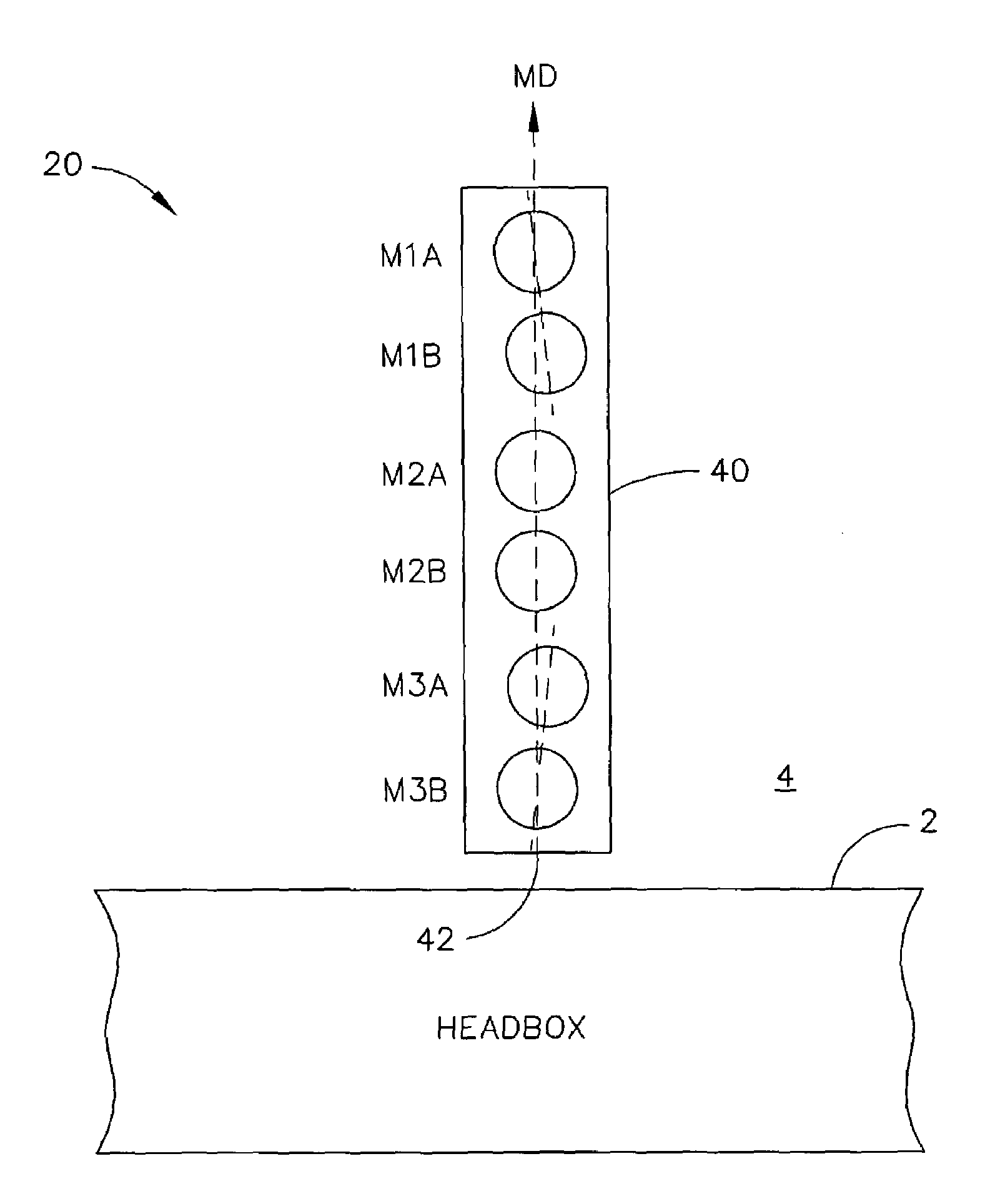
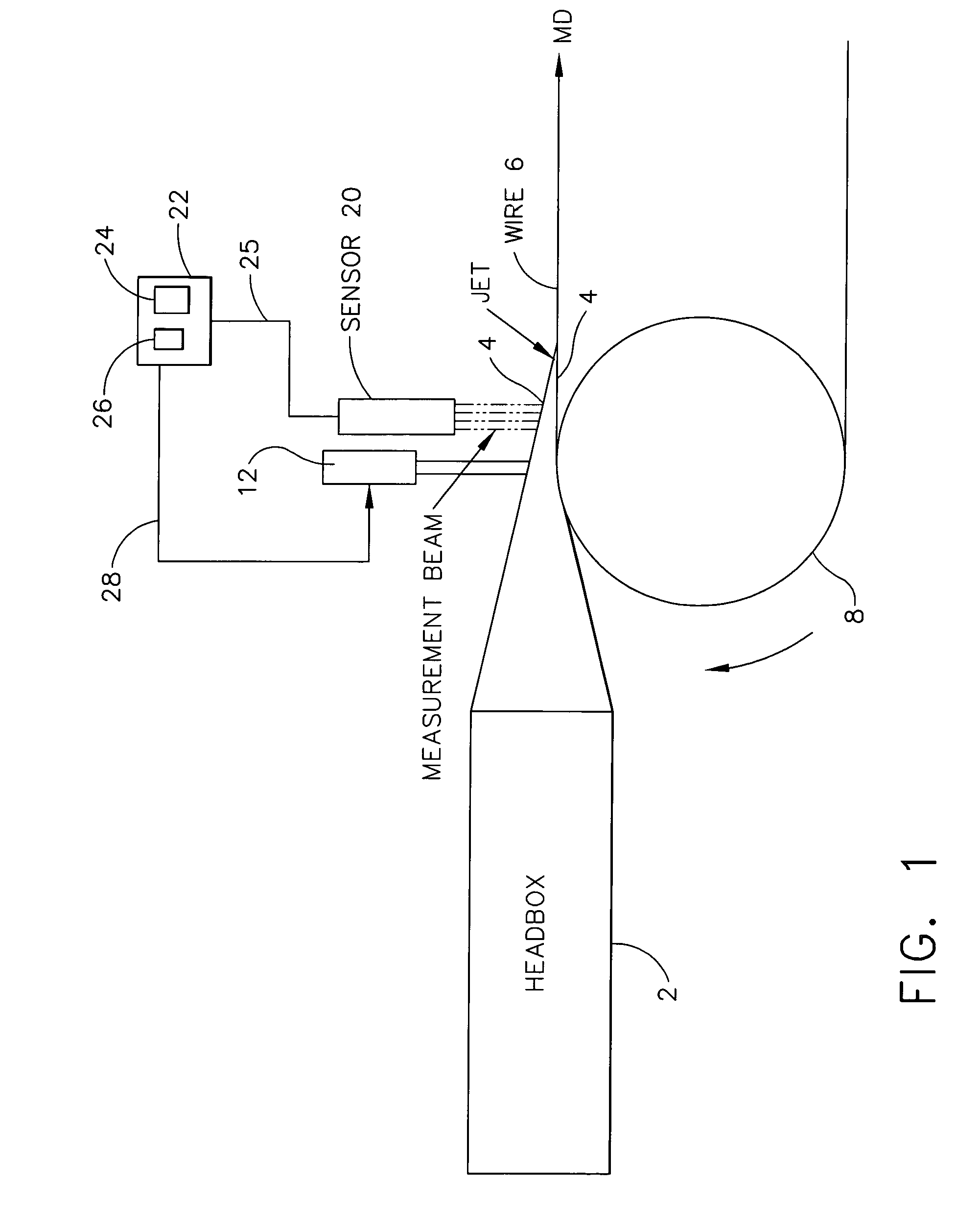
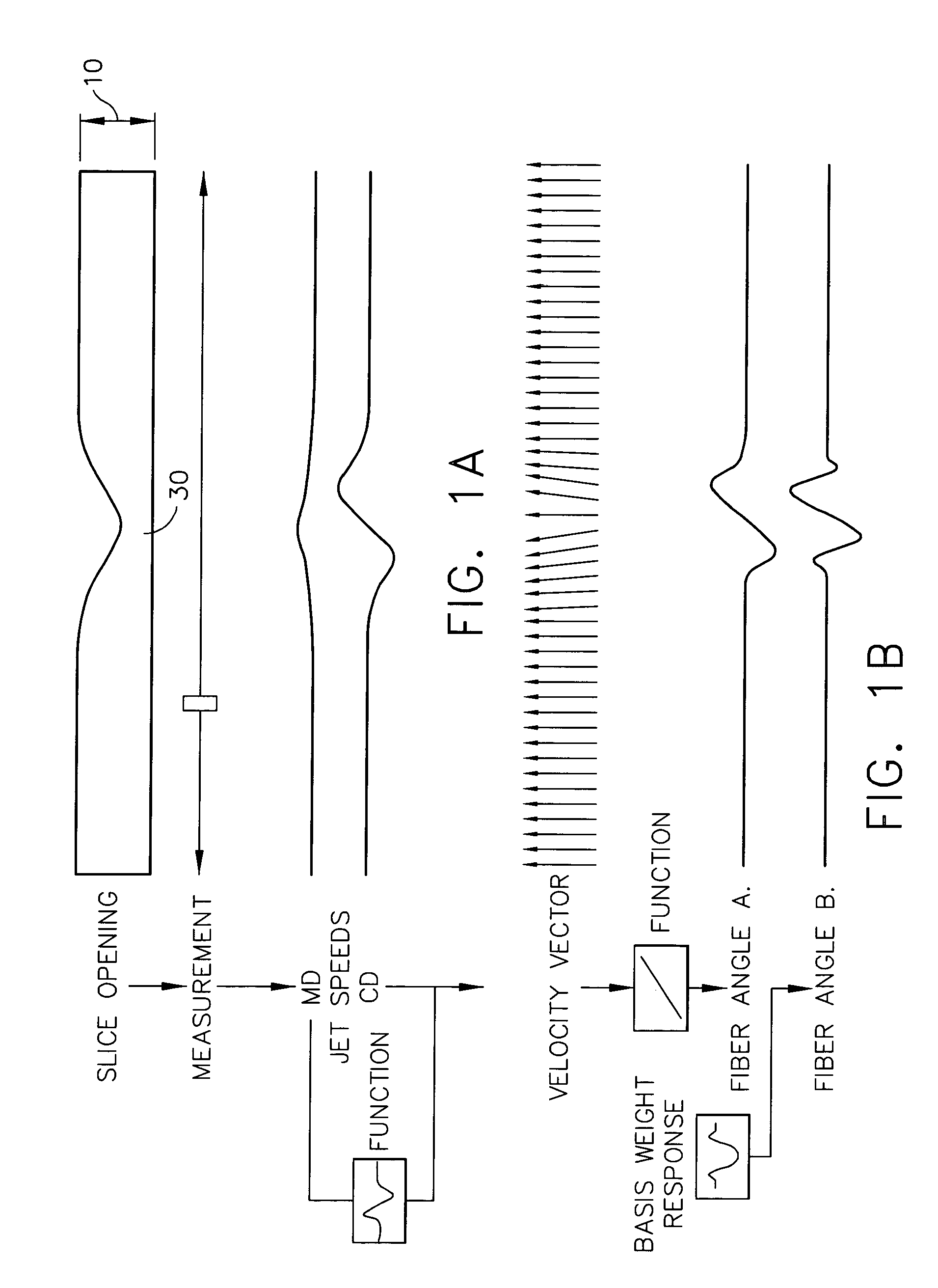
[0035]Referring to FIG. 1, there is shown schematically a headbox arrangement incorporating the present invention. The headbox 2 dispenses a jet 4 of liquid and paper forming fibers onto a moving Fourdrinier wire or screen 6. The headbox contains a slurry of liquid and paper forming fibers which is generally agitated in some manner to maintain a uniform mixture. Screen 6 moves in the machine direction (MD) by virtue of being an endless loop which is wound about rollers 8 rotating in a clockwise direction as indicated by arrow 9 in FIG. 1. An elongated slice opening 10 extends in the cross-machine direction (CD) transverse to the machine direction and provides an exit through which jet 4 leaves headbox 2 to form a liquid / fiber mat on screen 6. Screen 6 allows for liquid to drain rapidly from the mat leaving fibers orientated on the mat. A plurality of slice opening actuators 12 are arranged along the slice opening at space intervals to locally control the dimensions of the opening an...


PUM


Abstract

In a papermaking system having a headbox to dispense a jet of liquid and paper forming fibers, an improvement comprising at least one sensor arrangement for simultaneously or sequentially measuring in at least one location the jet velocity or jet flow correlation of the jet at plural known angles relative to the machine direction. The measured data is analyzed to generate a velocity vector profile or velocity direction profile of the jet, and hence to determine the profile of fiber orientation angles laid down in the sheet formed of the jet.

Description

FIELD OF THE INVENTION[0001]This invention relates generally to the field of papermaking, and particularly to a system for measuring and controlling the velocity or direction of a jet emerging from a slice in a head box.BACKGROUND OF THE INVENTION[0002]In the field of papermaking, the production of a sheet of paper begins at a headbox which contains a slurry of liquid and pulp containing paper forming fibers. The headbox has an elongated opening or slice lip through which the slurry under pressure is deposited onto a moving Fourdrinier wire or screen. The screen assists in separating the fibers from the liquid to create a web of material which is the initial step in the papermaking process.[0003]At the headbox, the slurry is deposited onto the wire and travels in the machine direction (MD). A series of actuators arranged along the cross-direction (CD) of the papermaking machine (transverse to the machine direction) control locally the size of the slice opening to permit the passage ...

Claims


Application Information

Patent Timeline
Patent Type & Authority Patents(United States)
IPC IPC(8): D21F7/06D21F1/02D21F1/06
CPCD21G9/0027Y10S162/11
Inventor FERM, JOHANHUBINETTE, ANDERSMACHATTIE, ROSS K.HALLGREN, ANDERSSHAKESPEARE, JOHN F.
Owner HONEYWELL INT INC
Why Eureka
Try Eureka