Variable potential electrokinetic devices

a potential electrokinetic and variable technology, applied in the direction of machines/engines, liquid/fluent solid measurement, peptides, etc., can solve the problems of limiting the use of electrokinetic pumps and flow controllers in many fluid handling applications, one or more shortcomings of prior art electrokinetic pumps and flow controllers, etc., to improve safety, operation efficiency, and compatibility with other instruments

Inactive Publication Date: 2008-07-15
TELEFLEX LIFE SCI PTE LTD
View PDF20 Cites 13 Cited by
  • Summary
  • Abstract
  • Description
  • Claims
  • Application Information

AI Technical Summary

Benefits of technology

[0012]The present invention provides variable potential electrokinetic devices including pumps and flow controllers that have improved performance, safety, operating efficiency, and compatibility with other instrumentation. The present invention achieves these objectives by providing in a first aspect, a variable potential electrokinetic device that comprises a pumping conduit having a first end and a second end, and containing a porous dielectric material; a conducting conduit having a first end and a second end, said pumping conduit second end and said conducting conduit first end connecting at a junction; and an odd number of electrodes in electrical communication with the pumping conduit and the conducting conduit.
[0014]In other preferred embodiments, V1 is equal to V3. This allows safety and compatibility to be optimized, by setting potentials V1 and V3 to, e.g., ground potential.
[0016]In another aspect, the invention provides a multi-stage electrokinetic device having a first pumping conduit having a first end and a second end, hydrodynamic conductance kp, electrokinetic pressure value pekp, and electrical resistance Rp and containing a first porous dielectric material; a first conducting conduit having a first end and a second end, hydrodynamic conductance kc, electrokinetic pressure value pekc, and electrical resistance Rc, the first pumping conduit second end connecting to the first conducting conduit first end at a first junction; a second pumping conduit having a first end and a second end, and containing a second porous dielectric material, said first conducting conduit second end and said second pumping conduit first end connecting at a second junction; and a first electrode in electrical communication with said first pumping conduit first end; a second electrode in electrical communication with said first junction; a third electrode in electrical communication with said second junction; and a fourth electrode in electrical communication with said second pumping conduit second end, wherein pekc / pekp<1 is required, wherein kc>kp is preferred to maximize performance and wherein Rc>Rp is preferred to increase electrical efficiency and reduce electrochemical evolution of the pumping fluid. These design principles also may be applied to the single-stage variable potential electrokinetic devices to obtain similar advantages.
[0017]In a related aspect of the multi-stage electrokinetic device, the invention provides for the first electrode to be at potential V1, the second electrode to be at potential V2, the third electrode to be at potential V3, and the fourth electrode to be at potential V4, so that at least one of the differences (V1−V2) and (V1−V2) is not equal to zero. In another preferred embodiment, V1 is equal to V4. This allows safety and compatibility to be optimized, by setting potentials V1 and V4 to, e.g., ground potential.
[0019]In a preferred embodiment of this multi-stage electrokinetic device, the odd number of electrodes comprises a first electrode at potential V1 in electrical communication with the first pumping conduit first end, a second electrode at potential V2 in electrical communication with the first junction, a third electrode at potential V3 in electrical communication with the second junction, a fourth electrode at potential V4 at the third junction, and a fifth electrode at potential V5 at the second conducting conduit second end, wherein at least one of the differences (V1−V2) and (V3−V4) does not equal zero. In another preferred embodiment, V1 is equal to V5. This allows safety and compatibility to be optimized, by setting potentials V1 and V5 to, e.g., ground potential.
[0020]In an alternative embodiment of the multi-stage electrokinetic device, the odd number of electrodes comprises a first electrode at potential V1 in electrical communication with said first pumping conduit first end, and an Nth electrode at potential VN in electrical communication with a second end of a terminal conducting conduit. In yet another preferred embodiment, V1 is equal to VN, which allows safety and compatibility to be optimized, by setting potentials V1 and VN to, e.g., ground potential.

Problems solved by technology

Notwithstanding these advantages, prior art electrokinetic pumps and flow controllers suffer from one or more shortcomings with respect to fluid composition, operating voltages, voltages at connection points to other devices, and pumping efficiencies that limit their use in many fluid handling applications.

Method used


Image

  • Variable potential electrokinetic devices
  • Variable potential electrokinetic devices
  • Variable potential electrokinetic devices

Examples


example 1

Construction of 1 Stage, Three Electrode Variable Potential Electrokinetic Pumps

[0156]Two variations of one stage, three electrode variable potential electrokinetic pumps, according to the embodiments illustrated in FIGS. 2c and 2d were constructed as follows. The pumping conduits were constructed by packing 1.6 μm nonporous silica beads (Bangs Laboratory, Inc., Fishers IN) in a 150 μm i.d. capillary (PolymicroTechnologies, LLC, Phoenix Ariz.) which was 5.5 cm in length. The particles, which when packed, provided the porous dielectric material, were contained in the capillary by sintering the particles to form frits of ˜1 mm with a thermal wire stripper. The conducting conduits were constructed using open capillaries (PolymicroTechnologies, LLC, Phoenix Ariz.) with 50 μm i.d. and 10 cm in length. The capillaries were connected together with conventional high-pressure fittings (Upchurch Scientific, Oak Harbor Wash.). Electrodes were constructed using a platinum wire in a fluid reserv...

example 2

Electrokinetic Pressure Multiplier

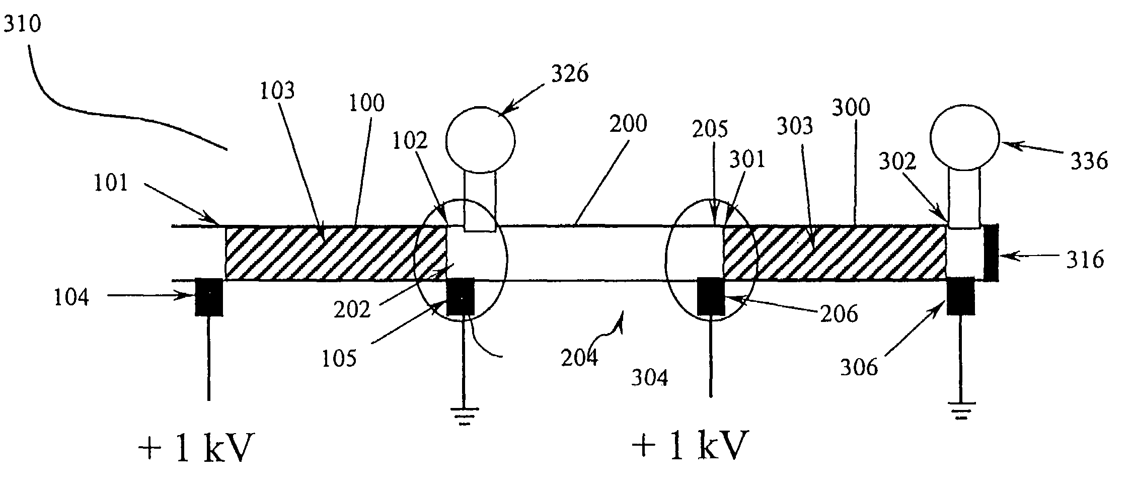
[0159]The two pumps constructed and tested in Example 1 were joined together with a high pressure low dead volume fitting to create an electrokinetic pressure multiplier that was tested with the same pumping fluid as used in Example 1. The configuration of the electrokinetic multiplier is illustrated in FIG. 9. The electrokinetic pressure multiplier was constructed in a similar fashion with similar components as the previous example of the variable potential electrokinetic pump. Pressure transducers 326, and 336 were attached to the electrokinetic pressure multiplier to permit monitoring of the pressure at junction, 204, and at the end, 302, of the second stage pumping conduit, 300; the outlet of the device was terminated into a fitting that was connected to the pressure transducer which permitted measurement of stagnation pressure. The two pumps were run in series in the amplification scheme and the pressure at the outlet was monitored. The amplifi...


PUM

PropertyMeasurementUnit
dielectric constantaaaaaaaaaa
electrical potentialaaaaaaaaaa

Abstract

Variable potential electrokinetic devices and electrokinetic multipliers used for pumping and flow control are disclosed that offer improvements in safety and design flexibility. The devices of the present invention take advantage of combinations of pumping conduits and conducting conduits to permit the use of lower operating voltages in pumps, pressure multipliers, and flow controllers. Devices having N pumping stages and 2N+1 electrodes permit the use of arbitrary voltages at the fluid connection points between the devices and other system components, further improving device safety and flexibility.

Description

CROSS-REFERENCE TO RELATED APPLICATIONS[0001]This is a continuation application claiming priority from U.S. patent application Ser. No. 10 / 066,528, filed Jan. 31, 2002, now U.S. Pat. No. 6,719,535 the contents of which are hereby incorporated by reference.STATEMENT REGARDING FEDERALLY SPONSORED RESEARCH[0002]Not applicable.REFERENCE TO A MICROFICHE APPENDIX[0003]Not applicable.BACKGROUND OF THE INVENTION[0004]The invention pertains to the fields of fluid handling and electroosmotic flow. More particularly, the invention pertains to variable potential electrokinetic devices useful as pumps and flow controllers.[0005]Electrokinetic pumps are useful for pumping fluids in a highly controllable manner. In addition, electrokinetic pumps provide advantages over mechanical pumps because the electrokinetic pumps may be manufactured with few or no moving parts. U.S. Pat. Nos. 6,013,164 and 6,019,882 describe the manufacture and use of the first electrokinetic pumps capable of generating press...

Claims


Application Information

Patent Timeline
Patent Type & Authority Patents(United States)
IPC IPC(8): G01N27/453F04B17/00F04B19/00
CPCF04B17/00F04B19/006Y10S977/932Y10S977/70
Inventor RAKESTRAW, DAVID J.NEYER, DAVID W.
Owner TELEFLEX LIFE SCI PTE LTD
Why Eureka
Try Eureka