
Method and apparatus for enhanced ion mobility based sample analysis using various analyzer configurations

a sample analysis and sample technology, applied in the field of mobility-based systems, methods and devices for analyzing samples, can solve the problems of difficult deployment, excessive cost of mass spectrometers, and high cost of mass spectrometers, and achieve enhanced sample analysis and enhanced sample identification

Inactive Publication Date: 2008-07-15
DH TECH DEVMENT PTE
View PDF97 Cites 43 Cited by
  • Summary
  • Abstract
  • Description
  • Claims
  • Application Information

AI Technical Summary

Benefits of technology

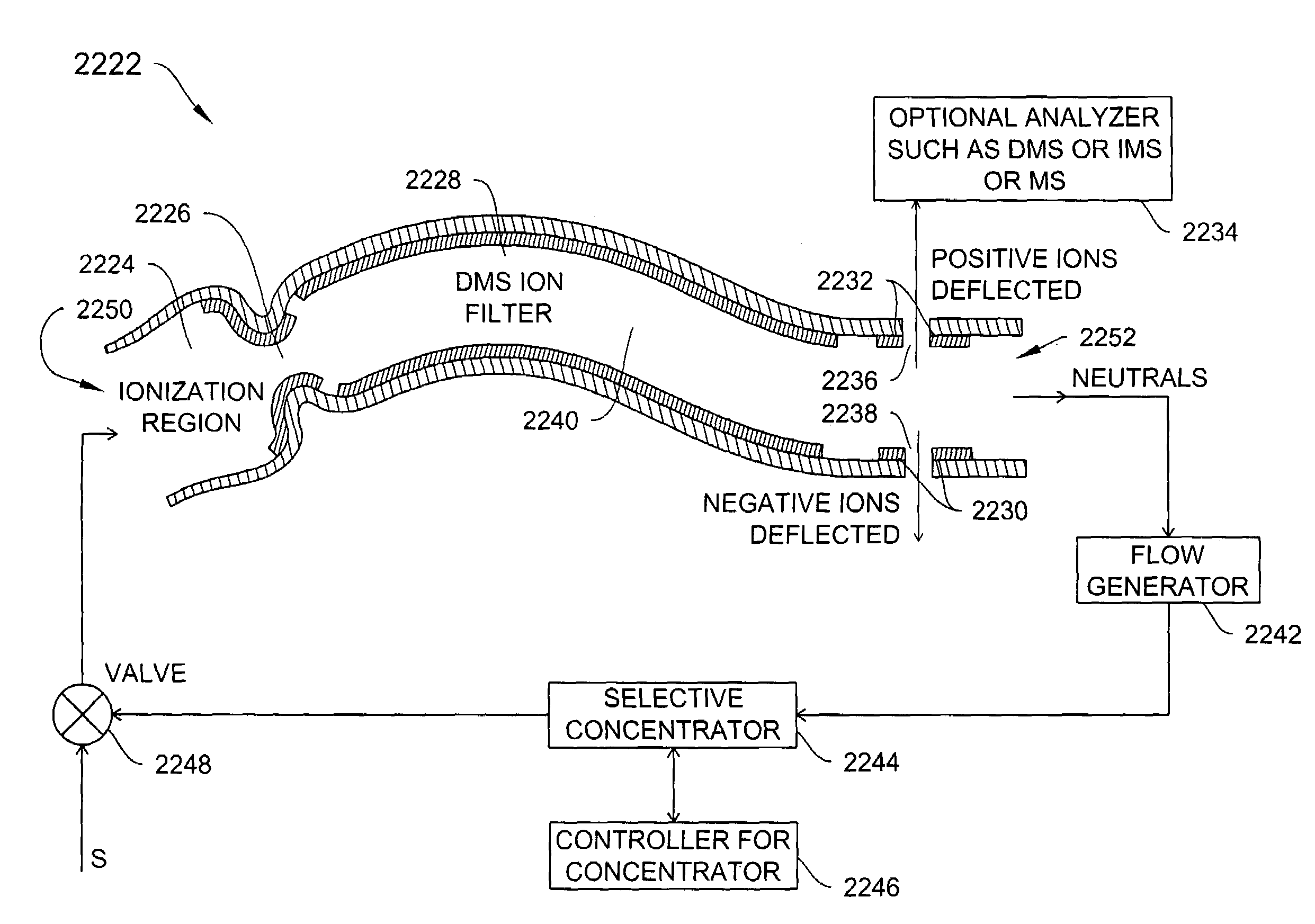
[0024]Sample analysis may be enhanced by, for example, combining DMS techniques with sample detection using another type of device such as IMS, TOF IMS, MS, electrochemical detector, or the like. In one illustrative embodiment of the invention, DMS filtering is combined with IMS detection in a U-shaped configuration to enhance sample identification.

Problems solved by technology

However, mass spectrometers are quite expensive, easily exceeding a cost of $100,000 or more and are physically large enough to become difficult to deploy everywhere the public might be exposed to dangerous chemicals.
Mass spectrometers also suffer from other shortcomings such as the need to operate at relatively low pressures, resulting in complex support systems.
Accordingly, mass spectrometers are generally difficult to use outside of laboratories.
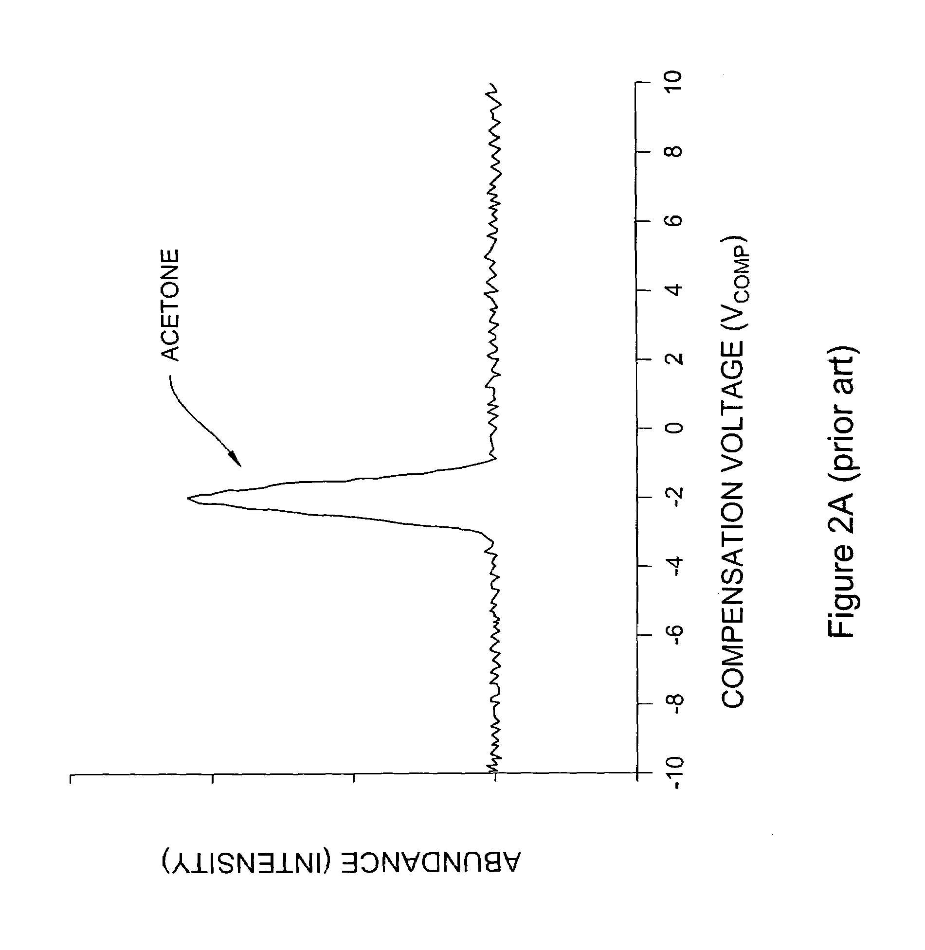
Therefore, compounds exhibiting intensity peaks at similar compensation voltages may be difficult to separate from each another.
In such a case, it is may not be possible to differentiate between the two different compounds.
Therefore, if two or more chemical species have the same or almost the same mobility characteristic, then their spectroscopic peaks will overlap, and identification and quantification of individual species will be difficult or impossible.
However, the sensitivity of these DMS / IMS systems has been degraded by the interaction of neutrals or other particles with ions during the detection process.

Method used


Image

  • Method and apparatus for enhanced ion mobility based sample analysis using various analyzer configurations
  • Method and apparatus for enhanced ion mobility based sample analysis using various analyzer configurations
  • Method and apparatus for enhanced ion mobility based sample analysis using various analyzer configurations

Examples


example 1

LTCC (Low Temperature Co-fired Ceramic) Standard, Simple Build

[0682]Start with three separate sheets of LTCC in green state.[0683]One defining channel spacer and shape[0684]print / deposit electrodes on top surface[0685]optional vias and side wrap[0686]One for electrode on bottom of channel[0687]form (e.g., laser cut, die cut, mill cut, EDM cut, water jet cut, LTCC ‘injection molding’, etc) desired channel shape into LTCC[0688]optional vias and side wrap[0689]One for electrodes on top of channels[0690]print / deposit electrodes on bottom surface[0691]optional vias and side wrap[0692]Laminate green sheets together with standard process[0693]Stack and align green sheets[0694]Heat to recommended temperature (e.g., 70 C)[0695]Apply recommended isostatic or axial pressure (e.g. 3000 psi)[0696]Fire as recommended by manufacturer[0697]Typically slowly heat to 400 C to 600 C range and hold to burn out organics[0698]Increase heat to 850 C range to solidify ceramic[0699]Cool[0700]Dice into indivi...

example 2

Advanced LTCC

[0701]See example 1[0702]Each of the following steps is optional and may be used alone or in combination with the others[0703]Use one or many layers of LTCC for channel spacer to create thicker or more complex geometries[0704]Use one or many layers of LTCC for top or bottom electrode layer for electrical, plumbing, heat transfer, mechanical, etc[0705]Fill empty spaces (e.g., gas flow channel) with sacrificial or removal filler material to maintain shape during lamination and / or firing[0706]Carbon tape[0707]Carbon ‘paste’[0708]Wax[0709]Metal inserts[0710]Plastic inserts[0711]Use jigs to align and hold sheets in place and provide additional or less support in critical areas[0712]Assemble and / or laminate green sheets in vacuum chamber[0713]Assemble and / or laminate green sheets at elevated temperature[0714]Assemble and fire some of layers, then add additional green sheet and fire again. Repeat as necessary for desired part[0715]Use adhesion promoter to minimize / simplify ass...

example 3

Alumina-LTCC Hybrid

[0717]See example 1[0718]Replace one or more of the green sheet layers with thick film alumina ceramic[0719]Example[0720]Replace top and bottom layers with thick film ceramic pre-coated with electrode design[0721]LTCC space layer now acts not only to form channel spacer and shape but also as the ‘glue’ bonding the two alumina ceramics into a single part[0722]This hybrid is not limited to alumina and LTCC. Can do the same with plastic, metal, ceramic, etc. parts / layers


PUM


Abstract

A system for analyzing one or more ion species of a sample including a first ion mobility filter associated with a first flow path for passing first ions of the sample, a second ion mobility filter associated with a second flow path for passing second ions of the sample, a first outlet from the first flow path for passing a portion of the first ions from the first flow path to the second flow path, and a first outlet from the second flow path for removing neutral particles from the second flow path where the first outlet from the second flow path is upstream of the second ion mobility filter in relation to the ion flow in the second flow path.

Description

REFERENCE TO RELATED APPLICATIONS[0001]This application is a continuation-in-part of U.S. patent application Ser. No. 11 / 190,691, filed on Jul. 26, 2005, which is a continuation of U.S. application Ser. No. 10 / 187,464, filed Jun. 28, 2002, now U.S. Pat. No. 7,045,776, which is a continuation-in-part of U.S. application Ser. No. 09 / 896,536 filed Jun. 30, 2001. U.S. patent application Ser. No. 10 / 187,464 claims the benefit of: U.S. Provisional Application No. 60 / 340,894, filed Oct. 30, 2001; U.S. Provisional Application No. 60 / 334,685, filed Nov. 15, 2001; U.S. Provisional Application No. 60 / 340,904, filed Dec. 12, 2001; U.S. Provisional Application No. 60 / 342,588, filed Dec. 20, 2001; and U.S. Provisional Application No. 60 / 351,043, filed Jan. 23, 2002.[0002]This application is also a continuation-in-part of U.S. patent application Ser. No. 11 / 011,949, filed on Dec. 13, 2004, which is a continuation of U.S. patent application Ser. No. 10 / 462,206, filed on Jun. 13, 2003, now U.S. Pat....

Claims


Application Information

Patent Timeline
Patent Type & Authority Patents(United States)
IPC IPC(8): B01D59/44H01J49/00
CPCH01J49/004G01N27/624
Inventor MILLER, RAANAN A.KRYLOV, EVGENYNAZAROV, ERKINJON G.EICEMAN, GARY A.WRIGHT, JOHN A.
Owner DH TECH DEVMENT PTE
Learn More