
Automated electrolyte addition for salt water pools, spas, and water features

a technology of automatic addition and salt water pool, which is applied in the direction of water treatment parameter control, water/sewage treatment by oxidation, filtration, etc., can solve the problems of water cloudiness, water in the pool or spa can be lost, and the efficiency of the system is reduced, and the effect of reducing the effect of the system

Active Publication Date: 2008-07-22
ECOLAB USA INC
View PDF9 Cites 19 Cited by
  • Summary
  • Abstract
  • Description
  • Claims
  • Application Information

AI Technical Summary

Benefits of technology

The present invention is an automated system that can add electrolyte to water, such as a pool or spa, to maintain a certain level of electrolyte concentration. The system includes a generator, a circulation system, and an electrolytic solution delivery system. The circulation system uses a suction line and a discharge line to deliver water from the body of water through a circulation path. The delivery system controls the introduction of electrolyte into the water. The technical effect of this invention is to provide a convenient and efficient way to maintain the proper electrolyte level in water.

Problems solved by technology

Allowing sanitation levels to either fall below or rise above required specifications results in decreased efficiency of the system.
Low levels of chemical sanitizer in the pool, spa, or water feature can contribute to algae blooms, bacterial breakouts, cloudiness in the water, and chemical imbalances.
Water in the pool or spa can be lost due to filter backwash, bather carry-out, and leaks in the infrastructure of the pool or spa body and plumbing.
Although this method is necessary during the start-up process due to the high initial charge of salt required to reach target concentrations, this procedure becomes a time-consuming project when dosing for maintenance purposes.
Manual addition of sodium chloride to a pool or spa also increases the risk of improperly dosing or adjusting the level of salt concentration in the pool.
Increased voltage and heat generation of the system can also increase when the level of electrolyte is below the required specification, potentially resulting in electrical component failures.
High levels of electrolyte in the pool can increase the potential for corrosion for pool equipment and pool surfaces.

Method used


Image

  • Automated electrolyte addition for salt water pools, spas, and water features
  • Automated electrolyte addition for salt water pools, spas, and water features
  • Automated electrolyte addition for salt water pools, spas, and water features

Examples


first embodiment

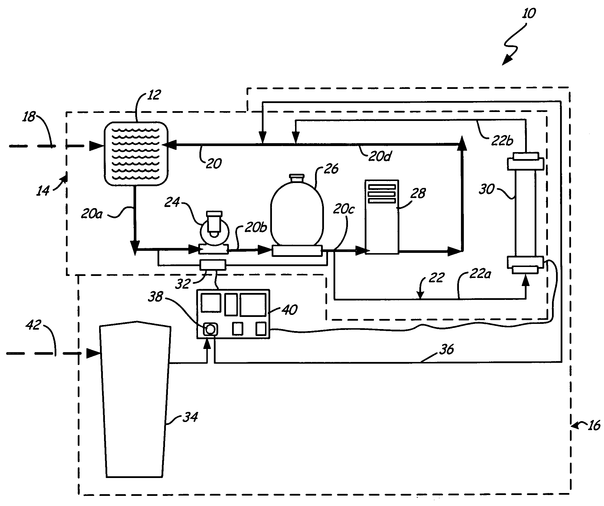
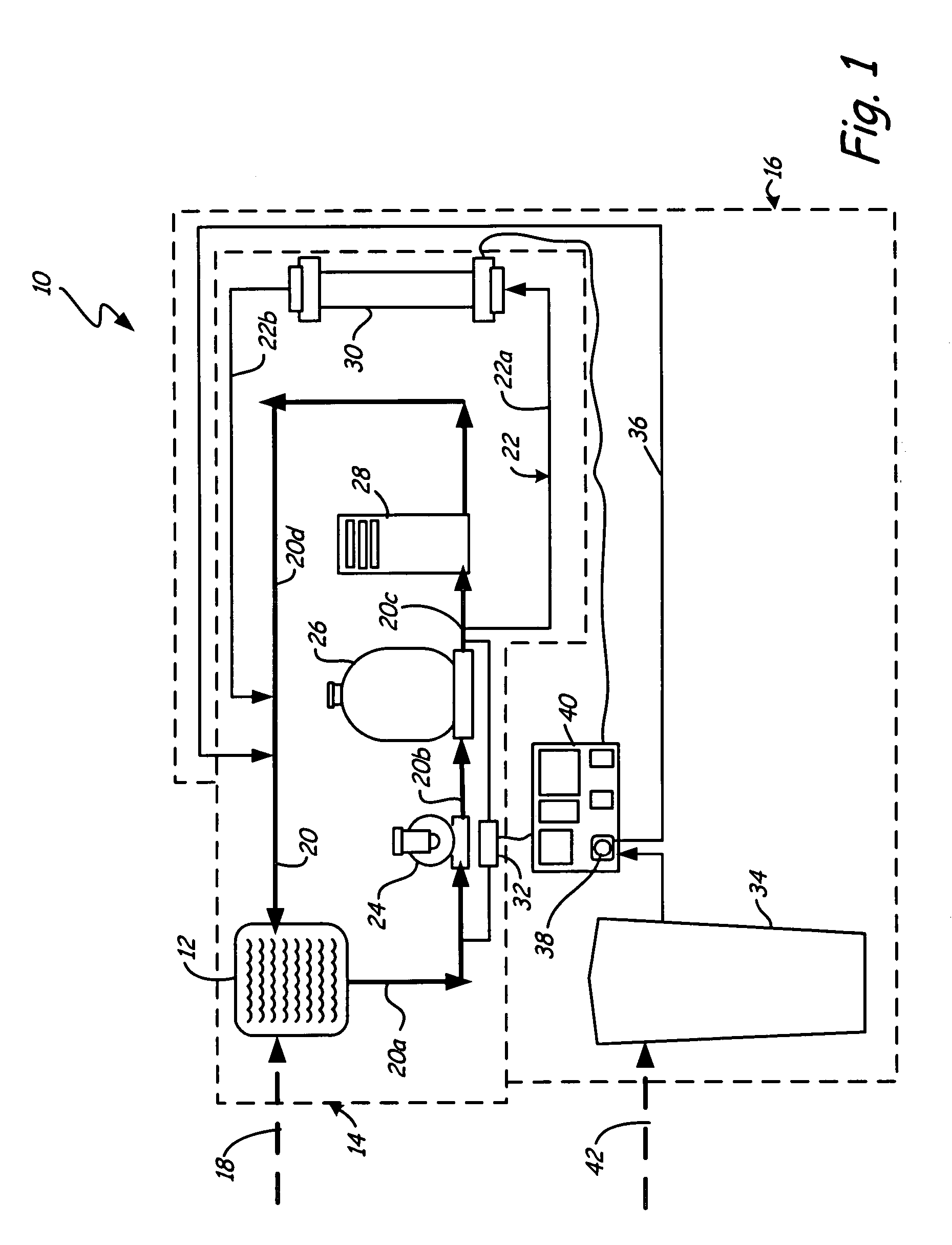
[0012]FIG. 1 is a schematic diagram of sanitization system 10 in accordance with the present invention. Sanitization system 10 is an automated system that maintains electrolyte concentration in a body of water, such as pool 12, by introducing an electrolytic solution, such as brine, into the water. Pool 12 may be any body of water to be treated, such as a swimming pool, spa, or other water feature. Automated addition of electrolyte to pools and spas is beneficial for reducing maintenance time of pool attendants and maintaining sanitizer concentrations in the body of water.

[0013]Sanitization system 10 generally includes circulation system 14, electrolytic solution feed system 16, and fresh water line 18. Circulation system 14 includes piping 20, side stream 22, circulation pump 24, filter 26, heater 28, sanitizer generator 30, and sensor 32. Electrolytic solution feed system 16 includes electrolytic solution vessel 34, feed stream 36, and electrolytic solution pump 38. Fresh water li...

second embodiment

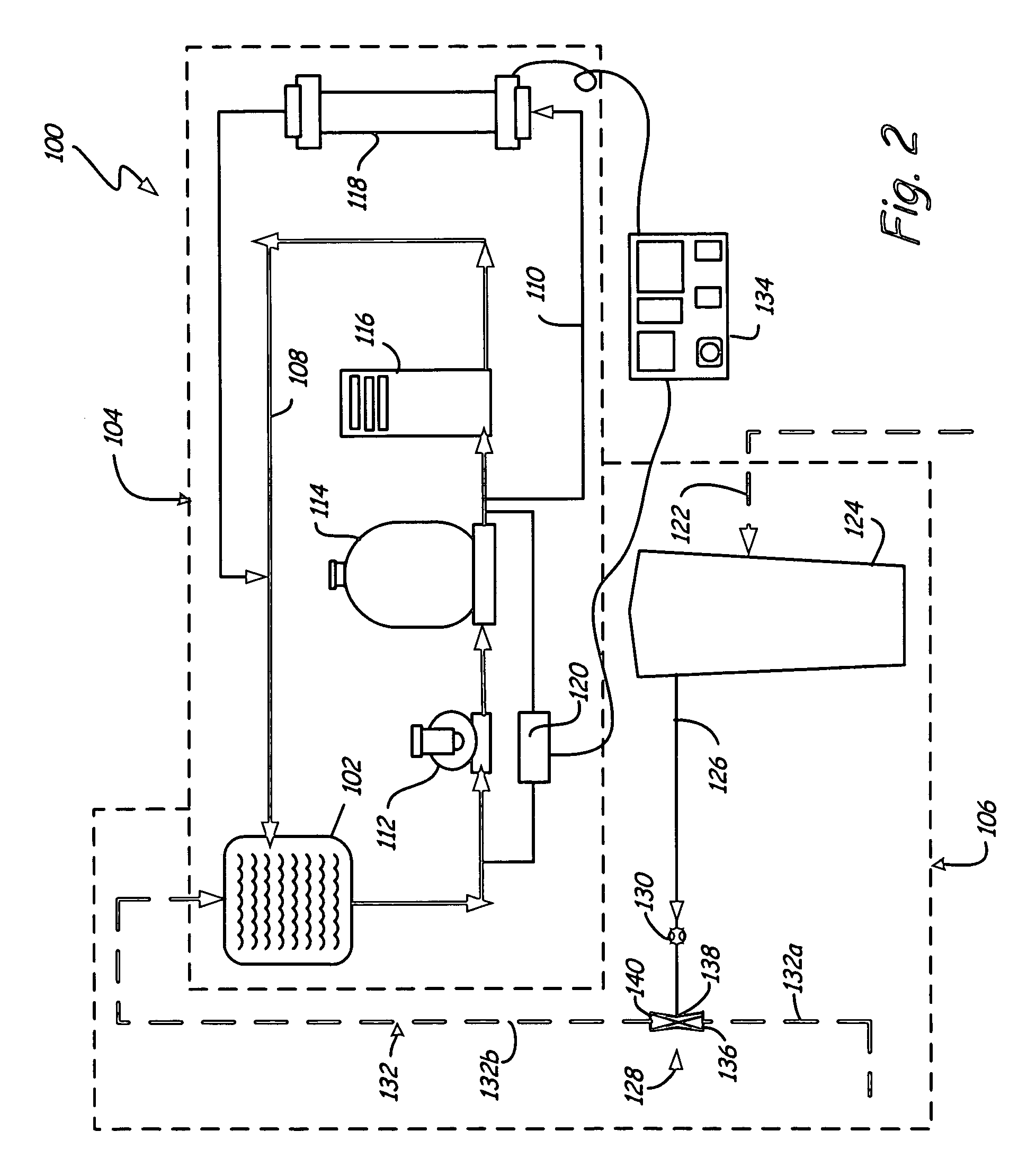
[0026]FIG. 2 shows a schematic diagram of automated sanitization system 100 connected to pool 102. Sanitization system 100 generally includes circulation system 104 and electrolytic solution feed system 106. Circulation system 104 includes piping 108, side stream 110, circulation pump 112, filter 114, heater 116, sanitizer generator 118, and sensor 120. Electrolytic solution feed system 106 includes fresh fill line 122, electrolytic solution vessel 124, feed stream 126, aspirator 128, valve 130, and fresh water lines 132a and 132b. Controller 134 is in communication with sensor 120 and controls sanitizer generator 118.

[0027]Circulation system 104 of sanitization system 100 is similar to circulation system 14 of sanitization system 10 in design and functionality with the exception that sensor 120 senses the oxidation-reduction potential (ORP), or sanitizer concentration, of the water flowing through circulation system 104. Electrolytic solution feed system 106 of sanitization system ...

third embodiment

[0031]FIG. 3 shows a schematic diagram of automated sanitization system 200 connected to pool 202. Sanitization system 200 generally includes circulation system 204, electrolytic solution feed system 206, and fresh water line 208. Circulation system 204 includes piping 210, side stream 212, circulation pump 214, filter 216, heater 218, sanitizer generator 220, and sensor 222. Electrolytic solution feed system 206 includes feed stream 224, pressure vessel 226, and metering valve 228.

[0032]Circulation system 204 and fresh water line 208 are similar to circulation system 14 and fresh water line 18 of sanitization system 10 in design and functionality with the exception of sensor 222. Sensor 222 and controller 230 function in the same manner as sensor 120 and controller 134 of sanitization system 100. Electrolytic solution feed system 206 of sanitization system 200 uses a continuous feed “trickle” method for adding electrolytic solution to pool 202 such that electrolyte is continuously ...


PUM

PropertyMeasurementUnit
pressure dropaaaaaaaaaa
conductivityaaaaaaaaaa
concentrationaaaaaaaaaa

Abstract

An automated system of the present invention adds electrolyte into a pool. The automated system includes a sanitizer generator, a circulation system, and an electrolytic solution delivery system. The circulation system, which includes the sanitizer generator, has a suction line and a discharge line that delivers water from the pool through a circulation path. The delivery system controls the introduction of electrolyte into the water.

Description

CROSS-REFERENCE TO RELATED APPLICATION(S)[0001]The present application is related to the concurrently filed applications Ser. No. 11 / 157,041, “Pool and Spa Dual Body Sanitizaition” and Ser. No. 11 / 157,073, “Dual Generator Single Power Source for Tandem Pool and Spa.”BACKGROUND OF THE INVENTION[0002]The present invention relates to the field of sanitizing pools and spas. In particular, the present invention relates to an automated system for adding an electrolytic solution (i.e. sodium chloride, potassium chloride, sodium chlorite etc.) to swimming pools, spas, and other water features.[0003]Pools, spas, and water features have a circulation system that continually pumps water from the pool or spa through a filter, heater, and sanitizer feed system before returning the water back to the pool, spa, or water feature. The circulation system is necessary to maintain the body of water at sanitary conditions. The water passes through the filter to reduce the accumulation of foreign materia...

Claims


Application Information

Patent Timeline
Patent Type & Authority Patents(United States)
IPC IPC(8): C02F1/50
CPCC02F1/76C02F1/001C02F1/02C02F1/4674C02F2209/005C02F2103/42C02F2209/003
Inventor KADLEC, LEONARD J.KILAWEE, PATRICK H.
Owner ECOLAB USA INC
Learn More