Modulation phase shift to compensate for optical passband shift

a phase shift and optical technology, applied in the field of optical networking, can solve the problems of the passband shift problem in the downstream optical demultiplexer, and achieve the effect of improving signal power

Inactive Publication Date: 2008-07-22
LUCENT TECH INC
View PDF7 Cites 17 Cited by
  • Summary
  • Abstract
  • Description
  • Claims
  • Application Information

AI Technical Summary

Benefits of technology

[0008]In one embodiment of the invention, an optical transmitter generates a chirped pulsed optical signal. As described in further detail below, a chirped pulsed optical signal is a signal in which each of a plurality of component wavelengths has peak power during its own time interval. Such a signal may result, for example, when a broadband pulsed optical signal is dispersed. Data is then modulated onto each of the component wavelengths for downstream transmission to an optical demultiplexer. Since the wavelengths of the chirped optical signal are dispersed in time, the modulator is synchronized such that appropriate data is modulated onto appropriate ones of the wavelengths during different time intervals. The downstream optical demultiplexer suffers from the passband shift problem described above. In accordance with the invention, the phase of the modulator is adjusted such that it modulates data onto wavelengths which substantially correspond to the new passband centers of the optical demultiplexer. Such dynamic adjustment of the phase of the modulator provides for improved signal power when the data reaches an end user.

Problems solved by technology

The downstream optical demultiplexer suffers from the passband shift problem described above.

Method used


Image

  • Modulation phase shift to compensate for optical passband shift
  • Modulation phase shift to compensate for optical passband shift
  • Modulation phase shift to compensate for optical passband shift

Examples


Embodiment Construction

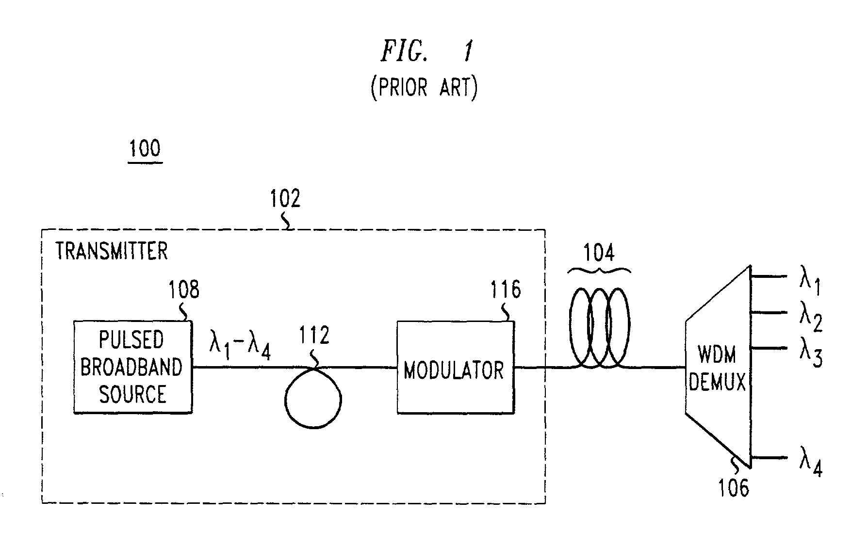
[0021]FIG. 1 shows an optical network 100 in accordance with the prior art, an understanding of which will assist in a description of the present invention. Network 100 includes a transmitter 102 which transmits a downstream chirped pulse optical signal to receivers (for example, ONU's at customer premises). The signal is comprised of 4 wavelengths λ1, λ2, λ3, λ4 and it travels via optical fiber 104 to a WDM demultiplexer 106 for distribution to the end users (not shown). It is noted that for purposes of the foregoing description, a WDM network utilizing four wavelengths will be described. However, one skilled in the art of optical networking would readily be able to implement the present invention using any number of wavelengths.

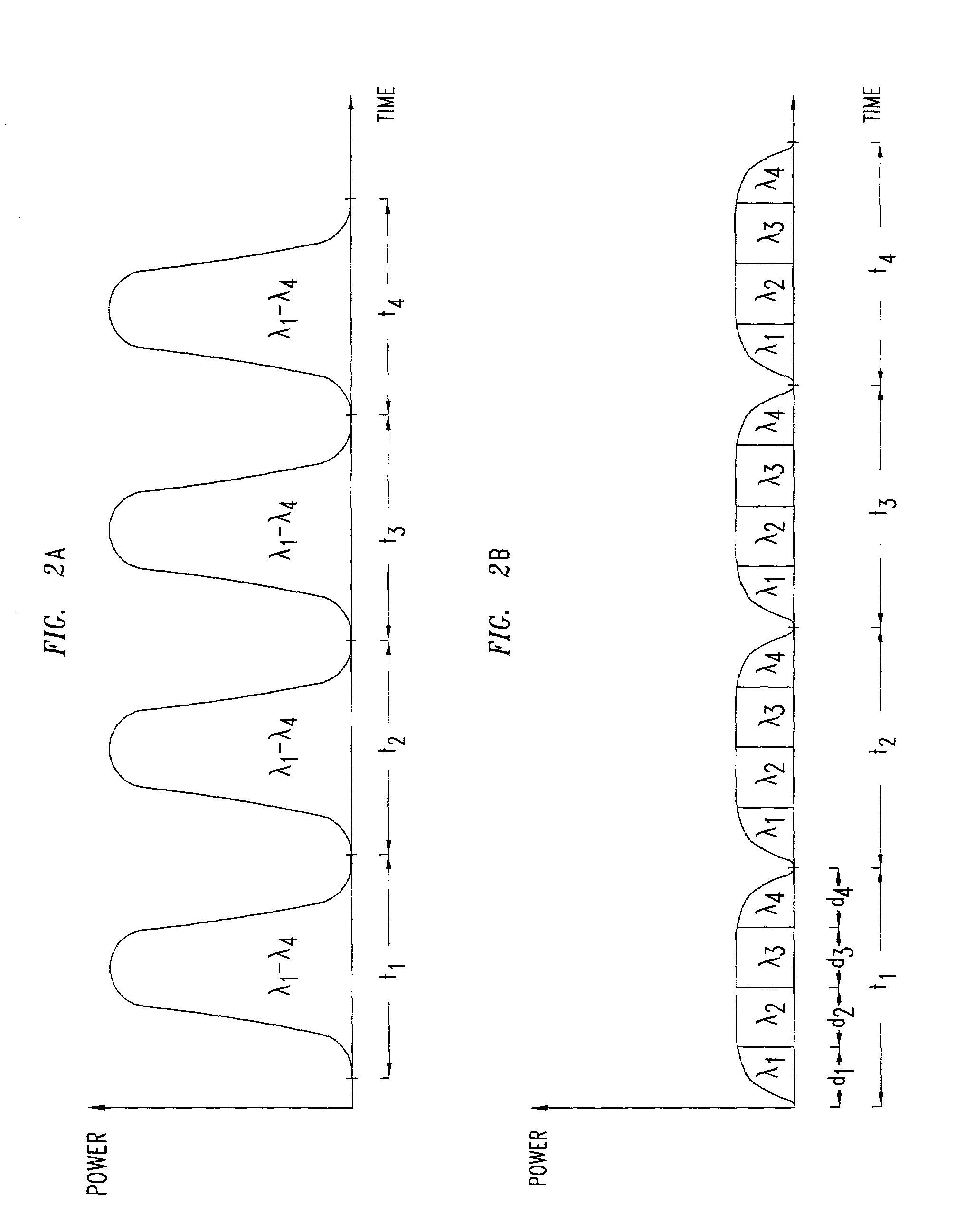
[0022]The functioning of the chirped pulsed optical transmitter and network of FIG. 1 will be described in further detail in conjunction with FIGS. 2A and 2B. Pulsed broadband source 108 generates broadband light pulses as illustrated in FIG. 2A. Each pulse...


PUM


Abstract

Disclosed is a technique for compensating for optical passband shift of an optical component (for example an optical demultiplexer). A broadband source coupled to a dispersive element generates a chirped pulsed optical signal. Data is modulated onto particular wavelengths of the chirped pulsed optical signal by appropriately synchronizing a data modulator. The modulated signal is transmitted to the downstream optical demultiplexer, which may be subject to passband shift due to, for example, changes in environmental conditions. A feedback signal from an output port of the demultiplexer is provided to the transmitter and is used to phase shift the modulator. The phase shift results in effectively adjusting the wavelength onto which the data is modulated to substantially correspond to the passband centers of the demultiplexer.

Description

TECHNICAL FIELD[0001]The invention relates generally to optical networking. More particularly, the invention relates to using a feedback mechanism to compensate for optical passband shift of a passive optical component.BACKGROUND OF THE INVENTION[0002]Optical networks use light to transmit information between points of the network. In a passive optical network (PON) the transmission facility between the transmitter and the receivers consists of passive (i.e., un-powered) optical components. Thus, once an optical signal leaves the transmission facility, the optical signals are routed to their destination via passive components, relying on the inherent properties of such components to ensure appropriate signal routing.[0003]One type of optical network which is becoming increasingly popular is the wavelength division multiplexed (WDM) network, which multiplexes multiple wavelengths of light on a single fiber for transmission through the network. Such systems provide for high bandwidth ...

Claims


Application Information

Patent Timeline
Patent Type & Authority Patents(United States)
IPC IPC(8): H04B10/04H04B10/155
CPCH04B10/505H04B10/58H04B10/50577H04B10/5057
Inventor MATTHEWS, MANYALIBO JOSEPHXU, CHUNHUI
Owner LUCENT TECH INC
Why Eureka
Try Eureka