Monitoring system for high-voltage switches

a high-voltage switch and monitoring system technology, applied in the field of engineering, can solve the problems of low resistance of the two contact systems, the need for transmission direct current to be so great, and the transportation cost of the test apparatus

Inactive Publication Date: 2008-07-29
ABB TECH AG
View PDF15 Cites 28 Cited by
  • Summary
  • Abstract
  • Description
  • Claims
  • Application Information

AI Technical Summary

Problems solved by technology

The fact that the transmitted direct current needs to be so great is because the resistances of the two contact systems are very low in value and differ from one another only slightly.
In addition to the transportation costs for the service personnel, transportation costs also arise for the test apparatus.

Method used


Image

  • Monitoring system for high-voltage switches
  • Monitoring system for high-voltage switches
  • Monitoring system for high-voltage switches

Examples


Embodiment Construction

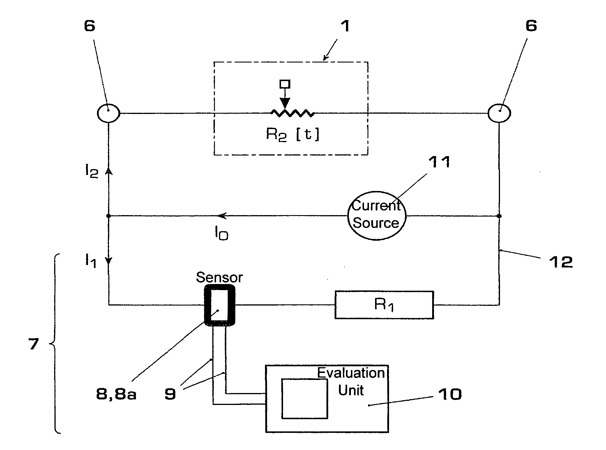
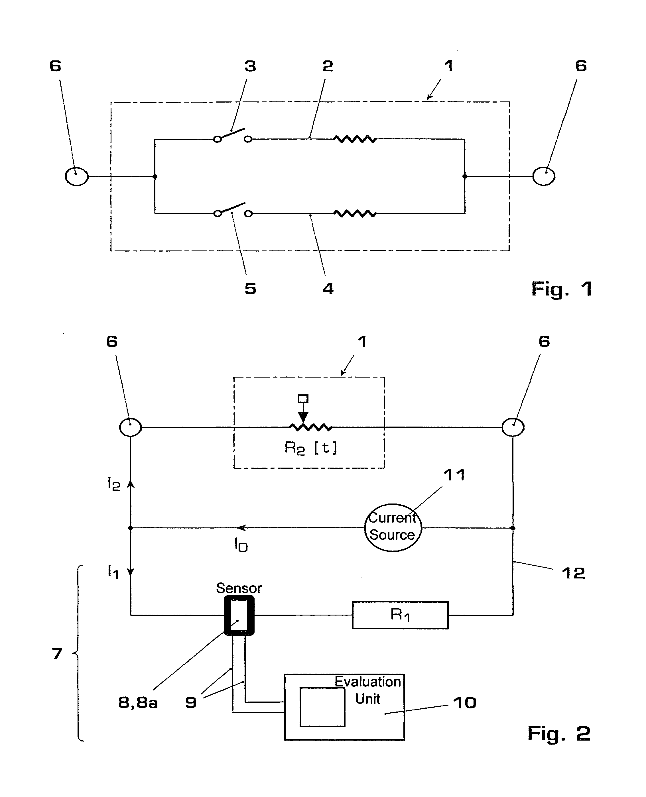
[0016]Circuit breakers 1, for example high-voltage circuit breakers, high current breakers (generator circuit breakers) or switch disconnectors, have in principle two contact systems, namely a rated current contact system 3 and an arcing or consumable contact system 5. The rated current contact system 3 has the task of transmitting the current in as loss-free a manner as possible when the switch 1 is closed. It is therefore distinguished by a very low line and contact resistance. The consumable contact system 5 only carries a notable current during the short time between opening of the rated current contacts 3 and it opening itself. The resistance of the consumable contact system 5 can therefore have a less significant role, and for this reason this resistance can be considerably greater than the resistance of the rated current contact system 3 in all circuit breakers 1.

[0017]FIG. 1 shows a schematic illustration of such a circuit breaker 1. In a tripping operation (open), the rated...


PUM


Abstract

A method and an apparatus are disclosed for measuring contact erosion in an electrical switching device by a dynamic resistance measurement (DRM). To determine an overlap time and a contact erosion in an exemplary switching device, a change in current across the switching device can be measured indirectly by a measurement current being passed across the switching device and a parallel conductor, the change in current in the parallel conductor being measured. Exemplary embodiments relate, to the following: detection of a differential current measurement signal in the parallel conductor with the aid of a Rogowski coil; and selection of a parallel conductor resistance on an order of the switch resistance.

Description

CROSS REFERENCE TO RELATED APPLICATIONS[0001]This application claims priority under 35 U.S.C. §119 to EP Application 05405679.1 filed in Europe on 30 Nov. 2005, the entire contents of which is hereby incorporated by reference in its entirety.TECHNICAL FIELD[0002]Features are disclosed regarding engineering, such as those relating to circuit breakers in electrical energy distribution systems. For example, a method and an apparatus are disclosed for monitoring a switching device.BACKGROUND INFORMATION[0003]Dynamic resistance measurement (DRM) is used for determining the overlap time of a circuit breaker. The overlap time is the time difference between the separation of the contacts in the rated current contact system and the separation of the contacts in the consumable or arcing contact system and indicates how severely the arcing contacts have already been eroded. It is therefore possible to assess the remaining life time of a quenching chamber. In the case of DRM, during CO operatio...

Claims


Application Information

Patent Timeline
Patent Type & Authority Patents(United States)
IPC IPC(8): G01R31/327
CPCG01R31/3271
Inventor HAGEL, MAREKFEHLMANN, PATRICK
Owner ABB TECH AG
Why Eureka
Try Eureka