Liquid crystal display with offset viewing cone

a liquid crystal display and viewing cone technology, applied in liquid crystal compositions, instruments, chemistry apparatus and processes, etc., can solve the problems of nb mode, achromatic light output in the optically active state of the liquid crystal display, and consuming minimum energy,

Inactive Publication Date: 2008-07-29
NITTO DENKO CORP
View PDF14 Cites 12 Cited by
  • Summary
  • Abstract
  • Description
  • Claims
  • Application Information

AI Technical Summary

Benefits of technology

[0058]FIG. 1A and FIG. 1B show the configuration of the liquid crystal molecules in the liquid crystal display with offset viewing cone of the invention in the on-state and off-state, respectively, where the reference numbers represent the following: 101—the director of the molecule in the midpoint of the rotation twist in the off-state of the liquid crystal, 103—the pre-tilt angle of the molecule adjacent to the alignment layer, 102—the pre-angle tilt of the molecule placed next to the molecule adjacent to the alignment layer in the off-state, 104, 105—alignment layers, 106—direction of the 90° rotation twist, 107—the angle of viewing offset, 108—the horizontal direction in the midpoint of the rotation twist, 109—the direction of the electrical field, 110—the liquid crystal molecules, 111—the pre-angle tilt of the molecule placed next to the molecule adjacent to the alignment layer in the on-state.
[0059]FIG. 2A presents a transmissive liquid crystal display with offset viewing cone, where the reference numbers represent the following: 201—light source, 202—initial light path cone, 203—light-directing liquid crystal cell, 204—contrast viewing cone after the liquid crystal light-directing cell, 205—the central angle of the contrast viewing cone produced by the liquid crystal light-directing cell. The figure shows the contrast viewing cone after the cell has shifted the center of the viewing volume relative to the initial direction.
[0060]FIG. 2B presents a reflective liquid crystal display with offset viewing cone. FIG. 2B shows contrast viewing cone after it is re-directed by the liquid crystal display relative to the initial direction. The viewing cone offset in the case of the reflective cell refers to a re-direction from the path of the mirror-reflected light.
[0061]FIG. 3 presents an application of

Problems solved by technology

Reflective LCDs use the light from ambient sources and employ no special backlighting systems, thus consuming minimum energy.
Therefore, a clear, achromatic light output in the optically active state of the liquid crystal display (bright state for the NW mode or dark state for the NB mode) is not possible in the general case.
In addition, the use of different optical phase compensators—i.e., optical retarders—can affect the LCD optical performance.
Although the use of the devices with wide viewing angle is possible in the cases when a specific off-normal viewing direction is required, this is generally not the best solution due to excessive light losses at non-viewable directions as well as unnecessary complexity and cost.
The main drawback of

Method used


Image

  • Liquid crystal display with offset viewing cone
  • Liquid crystal display with offset viewing cone
  • Liquid crystal display with offset viewing cone

Examples


Embodiment Construction

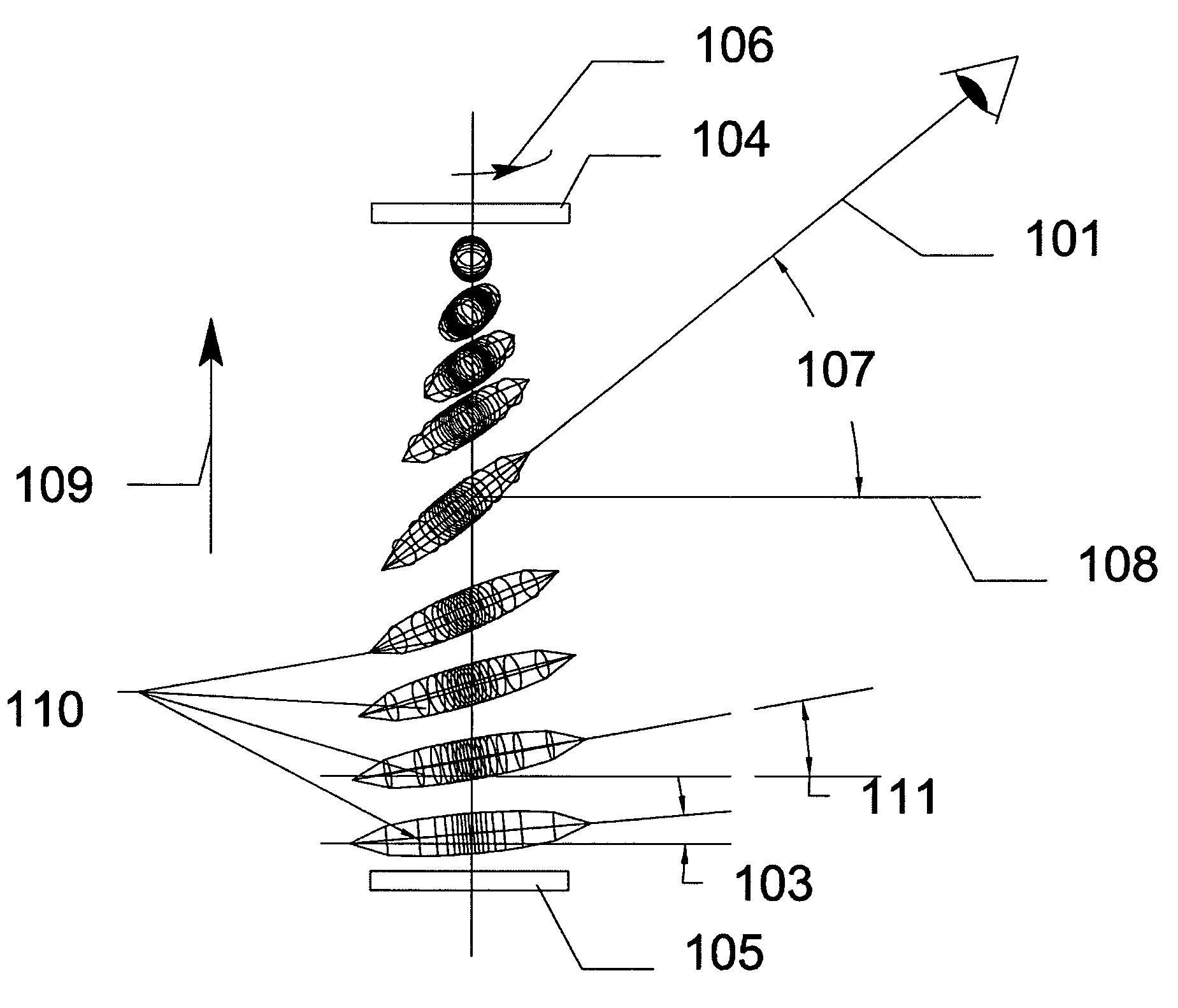
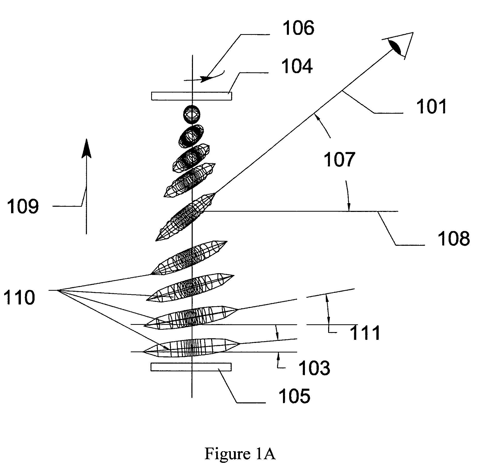
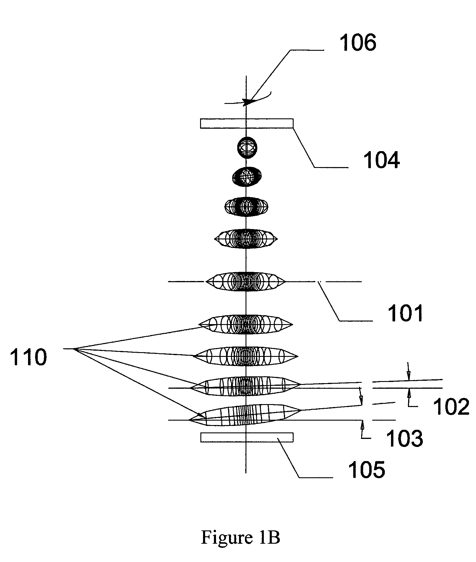
[0031]The present invention provides a highly effective liquid crystal display with a directed, offset viewing cone, which is simple and easy to fabricate. The liquid crystal display of the invention can be transmissive, reflective or transflective, and is capable of deflection of the viewing cone of maximal image contrast and brightness to a selected off-normal direction. Particularly, the transmissive variant allows deflection of the viewing cone from the straight light path, while the reflective variant allows deflection of the viewing cone from the mirror-like light path. This capability can be used in image display devices of various purposes, especially where such devices must be located in an offset position relative to the viewer.

[0032]The liquid crystal display of the invention comprises a plurality of layers, particularly, liquid crystal, substrates, polarizers, electrodes, and alignment layers etc. The liquid crystal layer is substantially the twisted nematic liquid cryst...


PUM


Abstract

A liquid crystal display is provided which comprises a front panel comprising a front alignment layer having an alignment direction, a rear panel comprising a rear alignment layer having an alignment direction, and a liquid crystal layer between the front and rear alignment layers. The liquid crystal layer has a rotational twist angle of about 90° and a pre-tilt angle of not more then 2°. The alignment, material and thickness of the liquid crystal layer are such that at the mid-point of the rotational twist, the direction of liquid crystal directors coincide with an off-normal viewing direction of the liquid crystal display.

Description

CROSS REFERENCES TO RELATED APPLICATIONS[0001]This application claims priority to the U.S. patent application Ser. No. 60 / 457,668, filed Mar. 25, 2003, the disclosure of which is hereby incorporated by reference.FIELD OF THE INVENTION[0002]This invention relates in general to the field of liquid crystal devices, and in particular to liquid crystal displays with offset viewing cone.BACKGROUND OF THE INVENTION[0003]Devices designed for off-normal, directed optical characteristics such as transmission, reflectance, contrast, brightness etc. are well known in the prior art. The optical anisotropy of nematic liquid crystals makes them ideal for use in these devices. The high level of development of liquid crystal materials and application methodology provide a solid technological foundation and facilitate their use in directed, light-modulating optical devices.[0004]In liquid crystal displays, light from front- or backlighting system or from ambient light sources sequentially passes thro...

Claims


Application Information

Patent Timeline
IPC IPC(8): G02F1/1337G02F1/1335G02F1/139
CPCG02F1/133528G02F1/1396G02F2001/133749G02F1/133749G02F1/1337G02F1/139
Inventor PAUKSHTO, MICHAEL V.SILVERSTEIN, LOUIS D.
Owner NITTO DENKO CORP
Why Eureka
Try Eureka