
Unified multi-carrier framework for multiple-access technologies

a multi-carrier, multi-carrier technology, applied in the direction of multi-path communication, digital transmission, electromagnetic transmission, etc., can solve the problems of increasing power consumption, flat fading, and no tone phase alignment, so as to reduce the effect of multi-path fading and interference, low power requirements, and reduced transmission power

Inactive Publication Date: 2008-07-29
DEPARTMENT 13 INC
View PDF16 Cites 152 Cited by
  • Summary
  • Abstract
  • Description
  • Claims
  • Application Information

AI Technical Summary

Benefits of technology

[0015]An objective of the invention is to reduce the effects of multipath fading and interference. A consequence of this objective is a significant reduction in required transmission power.
[0017]Another objective of the invention is to reduce interference to other systems and minimize the susceptibility of the communication system to all types of radio interference.

Problems solved by technology

However, the amplitude of each carrier is affected by the Rayleigh law, hence flat fading occurs.
A Rake receiver in an optimal DS-CDMA system uses a fast serial type of signal processing, which results in greater power consumption.
Furthermore, due to the binary-phase coding, no tone phase alignment is provided that is capable of conveying data symbols on orthogonal tone superpositions.
Thus, GHM does not provide carriers with phase relationships that enable precise time-domain control of the carrier superpositions.
Accordingly, GHM is not capable of expressing orthogonality in the time domain or reducing peak-to-average-power ratio (PAPR) problems associated with other multi-carrier protocols.
Similarly, GHM is not capable of forming waveforms that are backwards compatibility with single-carrier protocols or other multi-carrier protocols.
In this case, frequency diversity is achieved at the expense of reduced bandwidth efficiency.

Method used


Image

  • Unified multi-carrier framework for multiple-access technologies
  • Unified multi-carrier framework for multiple-access technologies
  • Unified multi-carrier framework for multiple-access technologies

Examples


Embodiment Construction

[0051]Various terms used in the descriptions of CI methods, systems, and waveforms are generally described throughout the specification. The descriptions in the specification are provided for illustrative purposes only, and are not limiting. The meaning of these terms will be apparent to persons skilled in the relevant art(s) based on the entirety of the teachings provided herein and in the referenced publications.

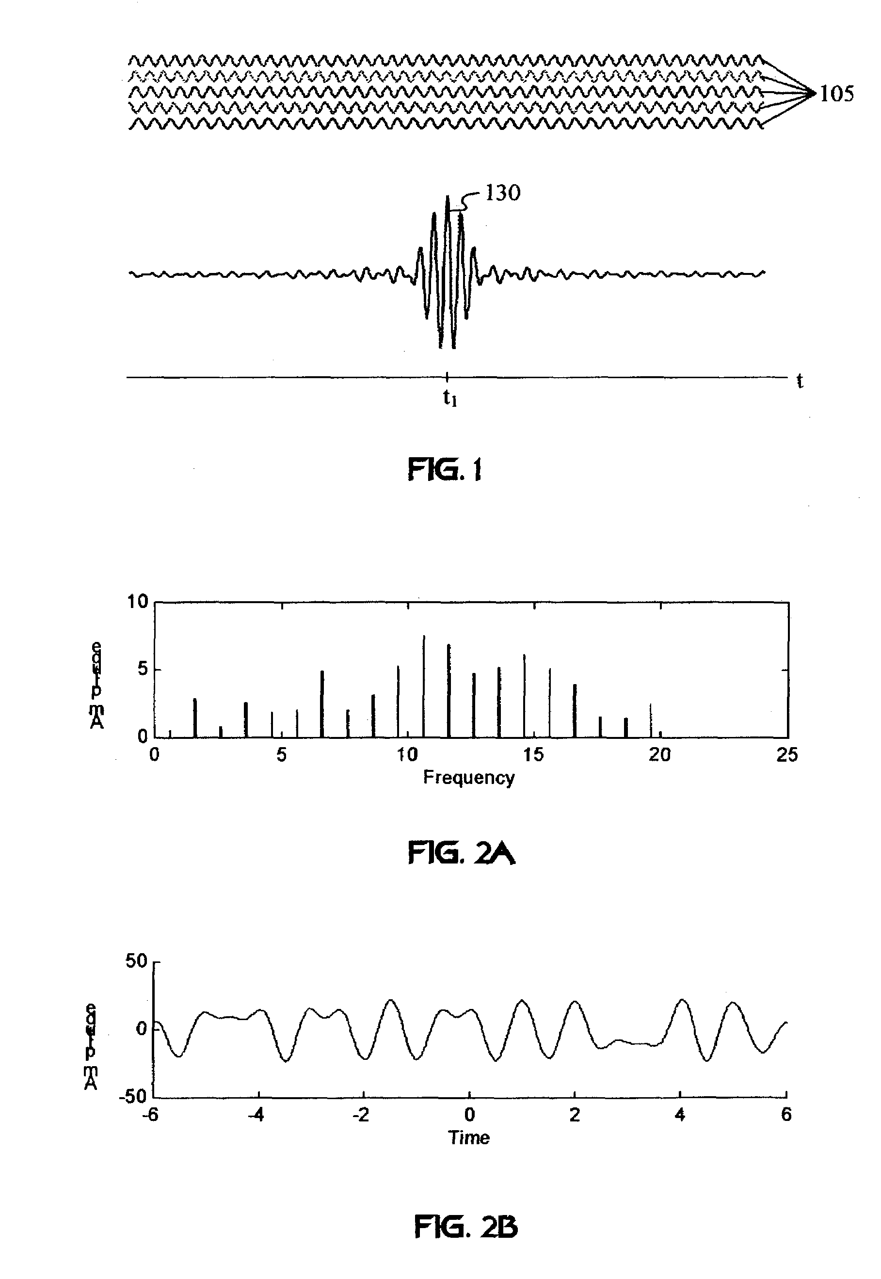
[0052]FIG. 1 illustrates a CI pulse shape characterized by an in-phase alignment (e.g., mode locking) of harmonic sub-carriers 105 at a specific time t1. Methods for generating CI signals may employ continuous-wave systems, such as the pulse generator shown in U.S. Pat. No. 5,955,992. For example, an impulse generator produces sub-carrier harmonics corresponding to the pulse repetition rate. Alternatively, CI pulse shaping may be implemented via sub-carrier generation circuitry, such as Fourier transforms described in WIPO Pub. App. No. WO 99 / 41871: “Multiple Access Method...


PUM


Abstract

A wireless communication system transmits data on multiple carriers simultaneously to provide frequency diversity. Orthogonality is provided by carrier interference, which causes a narrow pulse in the time domain corresponding to each transmitted data symbol. Selection of the frequency separation and phases of the carriers controls the timing of the pulses. Equivalently, pulse waveforms may be generated from an appropriate selection of polyphase sub-carrier codes. Time division of the pulses and frequency division of the carriers may be employed for multiple access. Received signals are processed by combining frequency-domain components corresponding to a desired user's allocated carriers. Individual data symbols are processed by providing polyphase decoding, matched filtering, or time-domain shifting the received carriers. Carrier Interferometry components may be used to build various signals corresponding to other transmission protocols.

Description

[0001]This patent application is a continuation-in-part of patent application Ser. No. 09 / 703,202, filed Oct. 31, 2000, now U.S. Pat. No. 7,076,168, issue date Nov. 7, 2006 which is a non-provisional of Provisional Patent Application No. 60 / 163,141, filed Nov. 2, 1999.FIELD OF THE INVENTION[0002]The present invention relates to a novel multicarrier spread-spectrum protocol for wireless and waveguide communications.BACKGROUND OF THE INVENTION[0003]Orthogonal Frequency Division Multiplexing (OFDM) has a high spectral efficiency (the spectrum of the subcarriers overlap) and combats frequency-selective fading. However, the amplitude of each carrier is affected by the Rayleigh law, hence flat fading occurs. Therefore, good channel estimation with an appropriate detection algorithm and channel coding is essential to compensate for fading.[0004]The performance of OFDM frequency diversity is comparable to the performance of an optimal direct-sequence CDMA (DS-CDMA) system's multipath divers...

Claims


Application Information

Patent Timeline
IPC IPC(8): H04J14/00H04L5/02H04L27/00
CPCH04L27/00H04L5/023
Inventor SHATTIL, STEVE J
Owner DEPARTMENT 13 INC
Learn More