Method and apparatus for transmitting a signal using thermal chirp management of a directly modulated transmitter

a transmitter and thermal chirp technology, applied in the field of direct modulated laser transmitters, can solve the problems of thermal electric coolers (tec) not being able to effectively eliminate thermal chirp, unwanted heating of semiconductor lasers, and thermal electric coolers (tec) not being able to react quickly enough to correct, etc., to reduce the “overshoot”, reduce the bit error rate, and reduce the optical signal-to-noise ratio (osnr).

Active Publication Date: 2008-07-29
II VI DELAWARE INC
View PDF13 Cites 24 Cited by
  • Summary
  • Abstract
  • Description
  • Claims
  • Application Information

AI Technical Summary

Benefits of technology

[0013]Another object of the present invention is to provide a method for reducing the “overshoots” in the optical waveform of a transmitter comprising a directly modulated laser and an optical spectrum (OSR) reshaper.
[0014]Still another object of the present invention is to decrease the bit error rate (BER) of a digital optical signal generated by a chirp managed directly modulated (CMDM) laser transmitter in an amplified system with a low optical signal-to-noise ratio (OSNR).
[0016]The present invention provides a modulation scheme for reducing the thermal chirp in a semiconductor laser, reducing the waveform overshoot, or decreasing the bit error rate (BER) of the data signal at a low optical signal-to-noise ratio (OSNR), by setting the pulse duty cycle to be higher or lower than 50% or the crossing point of the pulse duty cycle to be higher or lower than 50%. The present invention also provides a scheme for adjusting the resulting offset in crossing point to a desired value, which may or may not be 50%, by using an optical spectrum reshaper (OSR), and thus achieve a reduced bit error rate (BER) after fiber transmission.
[0020]the crossing point of the digital base signal is adjusted to reduce the thermal chirp of the optical signal.

Problems solved by technology

One of the difficulties in implementing a chirp managed directly modulated (CMDM) laser transmitter is the distortion caused by conversion of thermal chirp to amplitude fluctuation after passage through the optical spectrum reshaper (OSR), which results from unwanted heating of the semiconductor laser upon current injection.
This poses a particular problem in telecommunication applications, inasmuch as the laser is modulated by a “random” (i.e., variable, and hence unpredictable) stream of digital data.
As a result, the thermal electric cooler (TEC) cannot react quickly enough to correct for the faster temperature changes brought about by the injection current, i.e., the thermal electric cooler (TEC) cannot effectively eliminate thermal chirp.
These random thermal wavelength shifts are therefor converted to amplitude (i.e., intensity) fluctuations after passage through the optical spectrum reshaper (OSR), thus leading to “noise” on the 1's and 0's of the digital data stream.
Chromatic dispersion also converts frequency modulation to amplitude (i.e., intensity) modulation, so that thermal chirp can be converted to unwanted “noise” on the 1's and 0's of the data stream, which in turn causes degradation of the bit error rate (BER) in a telecommunications system.
This optical amplifier restores the amplitude of the signal, but at the cost of adding noise to the signal.
After undergoing several amplified spans, the optical signal-to-noise ratio (OSNR) degrades, causing the bit error rate (BER) to increase.
Non-linearity and dispersion, as well as other fiber transmission impairments, also degrade the quality of the signal as it passes down the fiber, and cause errors in the data stream.

Method used


Image

  • Method and apparatus for transmitting a signal using thermal chirp management of a directly modulated transmitter
  • Method and apparatus for transmitting a signal using thermal chirp management of a directly modulated transmitter
  • Method and apparatus for transmitting a signal using thermal chirp management of a directly modulated transmitter

Examples


Embodiment Construction

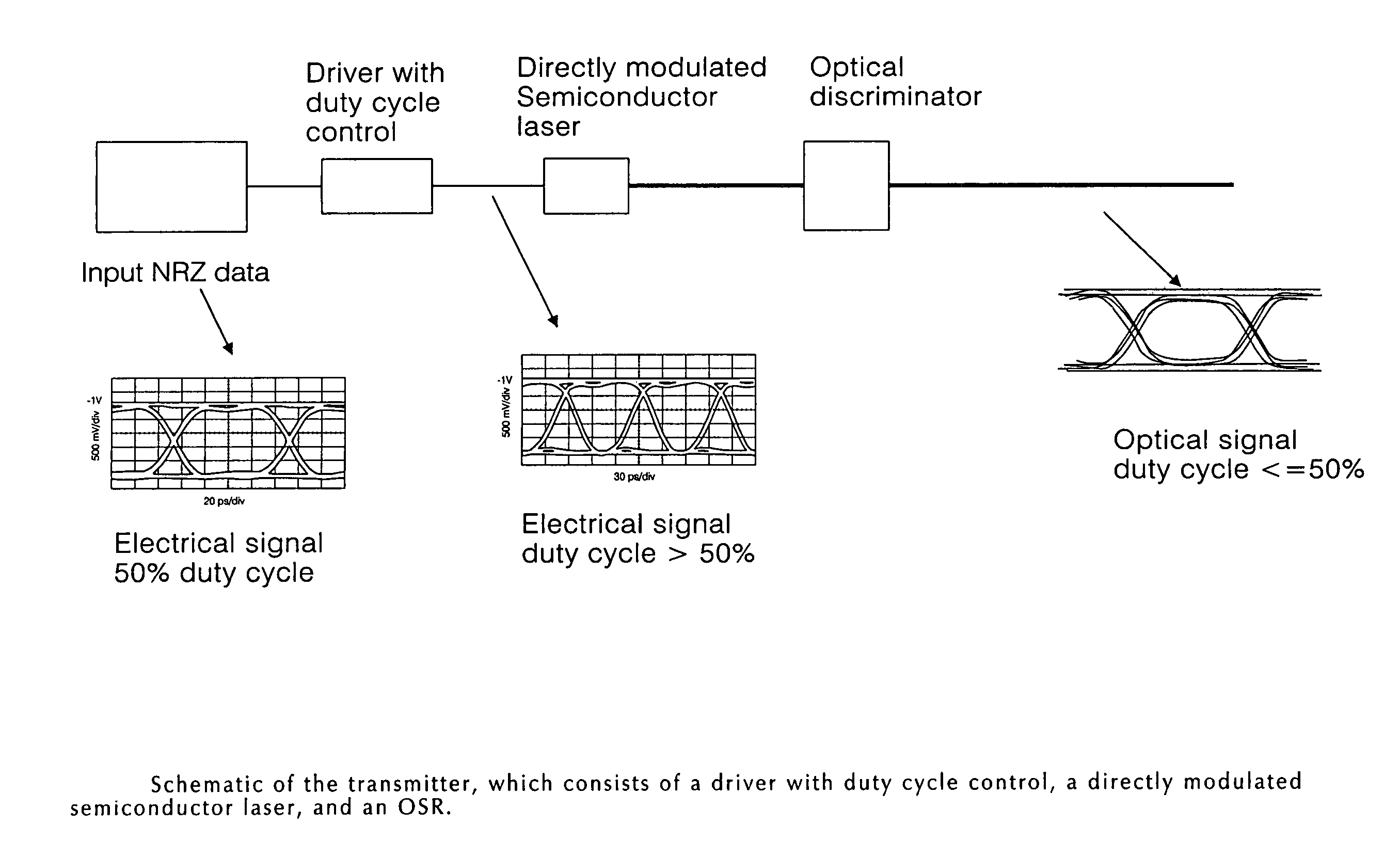
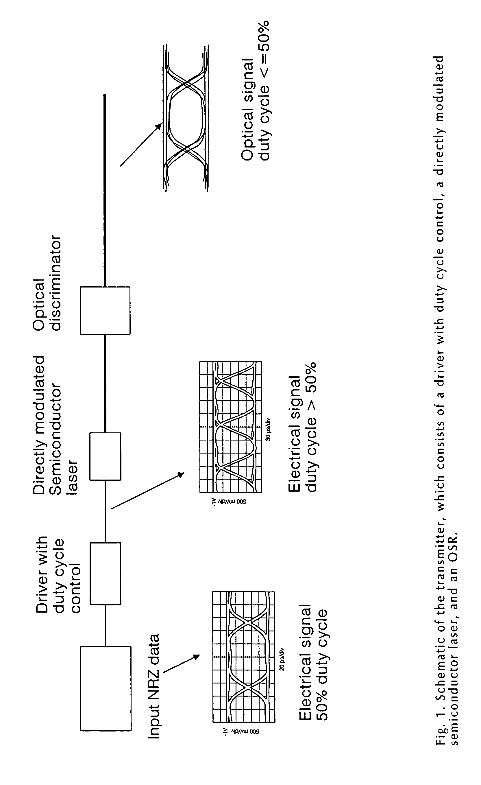
[0044]Looking first at FIG. 1, there is shown a Chirp Managed Directly Modulated laser (CMDML) transmitter which comprises a driver with duty cycle control (described below), a directly modulated semiconductor laser, and an optical spectrum reshaper (OSR), which may also be referred to as an optical discriminator (OD) or frequency discriminator (FD). In accordance with the present invention, the semiconductor laser is driven with a duty cycle higher than 50% to reduce the thermal chirp, and the optical signal reshaper (OSR) is used to reduce the duty cycle back to 50% (or a desired value, which may be different from 50%) before the signal is transmitted down the fiber.

[0045]Digital data consists of 1's and 0's, at a bit rate, B=1 / T, where T is the bit period. For a B=10 Gb / s system, T=100 ps. The 1 and 0 bits each occupy time durations τ1, and τ0, respectively, such that

τ1+τ0=2T.  (1)

[0046]The duty cycle is defined as the fraction of the duration of the 1's to twice the bit period:

D...


PUM


Abstract

A fiber optic transmitter comprising a digital driver adapted to adjust the crossing point of a digital base signal, an optical source adapted to receive the digital base signal and produce a frequency modulated optical signal, and an optical spectrum reshaper adapted to convert the frequency modulated optical signal to an amplitude modulated optical signal.A method for transmitting a signal, comprising:adjusting the crossing point of a digital base signal;providing the adjusted signal to an optical source to produce a frequency modulated optical signal; andproviding the frequency modulated optical signal to an optical spectrum reshaper to convert the frequency modulated optical signal to an amplitude modulated optical signal.

Description

REFERENCE TO RELATED APPLICATION[0001]This patent application is a continuation-in-part (CIP) of prior U.S. patent application Ser. No. 10 / 289,944, filed Nov. 6, 2002 now U.S. Pat. No. 6,963,685 by Daniel Magherefteh et al. for POWER SOURCE FOR A DISPERSION COMPENSATION FIBER OPTIC SYSTEM.[0002]This patent application also claims benefit of:[0003](i) pending prior U.S. Provisional Patent Application Ser. No. 60 / 500,540, filed Sep. 5, 2003 by Daniel Magherefteh et al. for THERMAL CHIRP MANAGEMENT OF DIRECTLY MODULATED TRANSMITTER;[0004](ii) pending prior U.S. Provisional Patent Application Ser. No. 60 / 530,479, filed Dec. 17, 2003 by Daniel Mahgerefteh et al. for OPTICAL TELECOMMUNICATIONS SYSTEM; and[0005](iii) pending prior U.S. Provisional Patent Application Ser. No. 60 / 557,538, filed Mar. 30, 2004 by Yasuhiro Matsui et al. for REACH EXTENSION BY USING EXTERNAL FIBER BRAGG GRATING FOR SPECTRAL FILTERING.[0006]The four above-identified patent applications are hereby incorporated her...

Claims


Application Information

Patent Timeline
Patent Type & Authority Patents(United States)
IPC IPC(8): H04B10/04G02B5/28G02B6/34H04B10/155H04B10/18
CPCG02B5/281G02B6/29358G02B6/29362H04B10/58H04B10/25133H04B10/504G02B6/29394G02B6/29398
Inventor MAHGEREFTEH, DANIELNUYTS, ROELANDMATSUI, YASUHIROTAYEBATI, PARVIZJOHNSON, BARTWALKER, DUNCANZHENG, XUEYAN
Owner II VI DELAWARE INC
Why Eureka
Try Eureka