Uniaxial thermal and/or mechanical deformation-measuring device system and method employing a Bragg grating optical fibre

a technology of mechanical deformation and measuring device, which is applied in the direction of thermometer, instrument, and sensor output, etc., can solve the problems of insufficient sensitivity of classically used bragg grating optical fiber to have a sufficient measurement resolution, and the inability to supply gauges with resolution,

Inactive Publication Date: 2008-08-05
COMMISSARIAT A LENERGIE ATOMIQUE ET AUX ENERGIES ALTERNATIVES
View PDF10 Cites 10 Cited by
  • Summary
  • Abstract
  • Description
  • Claims
  • Application Information

AI Technical Summary

Benefits of technology

[0044]In other words, the length L of the section of Bragg grating optical fiber stressed to carry out the measurements of deformations can be changed so that this length is less than the length of the measurement body Lce by a factor K. In this case, the relative displacement ΔλB / λB of the characteristic wavelength of a Bragg grating is increased by this factor K, thus facilitating the measurement of this variation.
[0072]The advantage which is gained by the increase in the effective index brought about by this microstructure, which may be a few percent, making it possible to increase the effective index of the fiber from a value of 1.46 to 1.50, for example, makes it possible to increase the sensitivity to any effect on the external parameters of the thus inscribed Bragg grating of the same order of magnitude.

Problems solved by technology

However, in some cases, the measuring sensitivity of a classical Bragg grating optical fiber device is insufficient to have a sufficient measurement resolution with respect to a temperature and / or a force, and more generally, a deformation.
In this case the sensitivity for measuring or detecting a Bragg grating optical fiber classically used as in the prior art is insufficient.
Such a resolution cannot be supplied by gauges of resistive electric deformations because, in fact, electromagnetic fields generated by the catenary wire interfere with the measurement signal supplied by these gauges.
According to other examples, variations in deformations to be measured of structures which are designed not to vary, such as buildings, bridges or water dams, may also be too low to be able to be measured satisfactorily with a classical device equipped with a Bragg grating optical fiber.

Method used


Image

  • Uniaxial thermal and/or mechanical deformation-measuring device system and method employing a Bragg grating optical fibre
  • Uniaxial thermal and/or mechanical deformation-measuring device system and method employing a Bragg grating optical fibre
  • Uniaxial thermal and/or mechanical deformation-measuring device system and method employing a Bragg grating optical fibre

Examples


Embodiment Construction

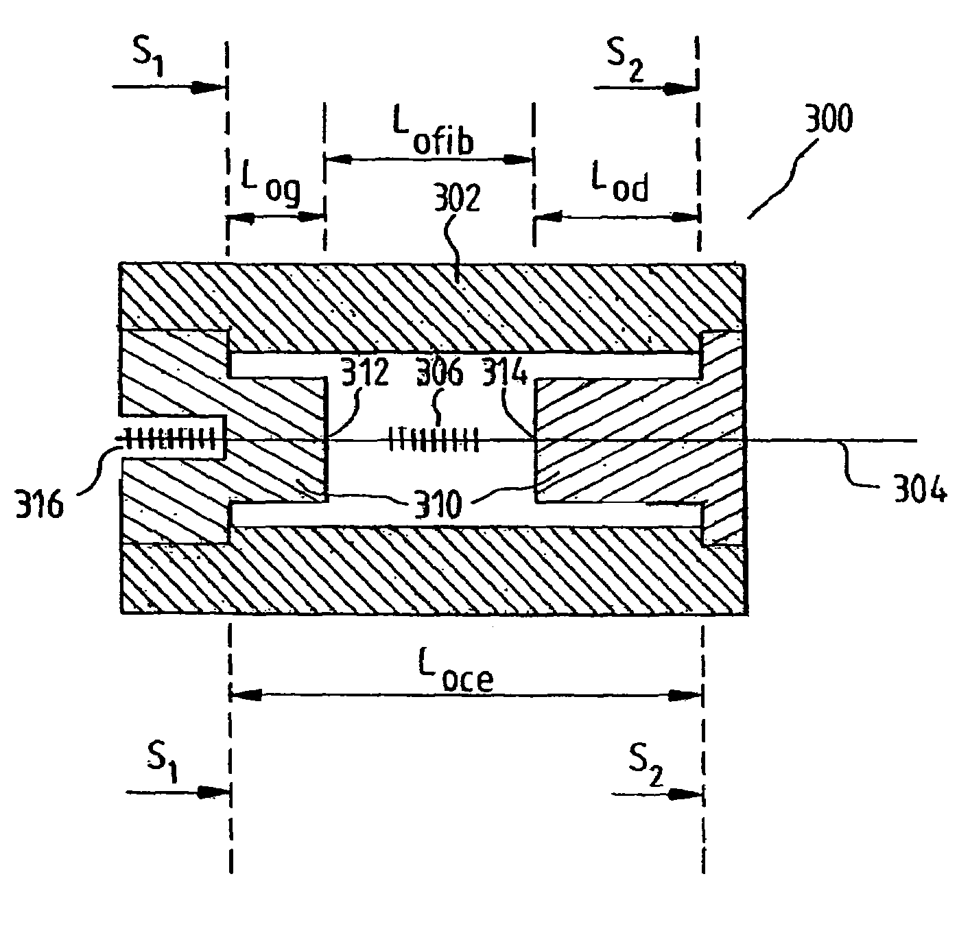
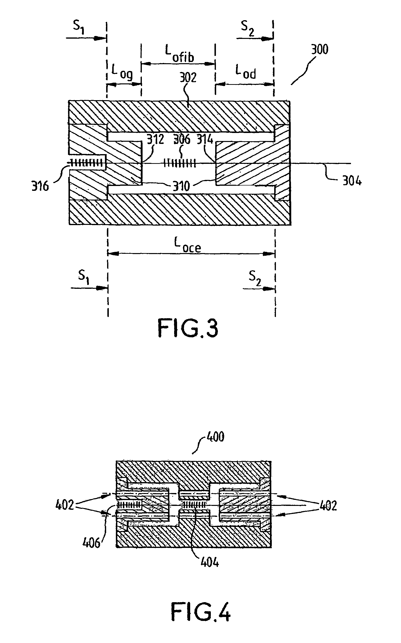
[0089]A first embodiment is described below with reference to FIG. 3, which shows a device 300 for measuring forces according to the present invention.

[0090]To determine the force applied on the test body 302 of this device, the longitudinal deformation Δεce of the latter is measured by means of a Bragg grating 306 optical fiber 304.

[0091]Knowing the thermomechanical properties of the test body, it is possible to determine the variation in load Δσ exerted on the device from the measurement of its longitudinal deformation Δεce, obeying, in elastic mode, Hooke's law:

Δσ=E·Δεce

[0092]where E is the modulus of elasticity of the material used for the test body. Knowing the section S of this test body at the location where the longitudinal deformation Δεce is measured, the variation in force ΔF exerted on same is deduced according to equation:

ΔF=Δσ·S

[0093]In practice, the section S of this test body is not necessarily constant. It is sufficient that the force or the uniaxial load, aligned w...


PUM

PropertyMeasurementUnit
spectral widthaaaaaaaaaa
elongationaaaaaaaaaa

Abstract

Uniaxial deformation-measuring device includes a section of optical fiber equipped with a Bragg grating aligned with the measurement axis, and a test body subjected to the deformations to be measured., this device includes the fixing points for attaching the fiber to the test body. The fixing points are separated by a distance (Lfib) having a variation (ΔLfib). When the test body is stressed by the deformation, the effective length (Lce) of the test body has an elongation (ΔLce). The length (Lfib) of the section of optical fiber and the effective length (Lce) of the measurement body are such that the longitudinal deformation (ΔLfib / Lfib) of the section of optical fiber is strictly greater than the originating deformation (ΔLce / Lce) of the test body, thus defining an amplification factor K which is strictly greater than 1 and which is equal to the quotient (ΔLfib / Lfib) / (ΔLce / Lce) in the first order.

Description

[0001]The present invention pertains to a uniaxial thermal and / or mechanical deformation-measuring device, system and method employing a Bragg grating optical fiber, particularly for measuring a force and / or a temperature.BACKGROUND[0002]An optical fiber 110 (FIG. 1) transmits an electromagnetic radiation 112, maintained in its optical core 114 due to a difference between the refractive index nc of the optical core 114 and the refractive index ng of the optical cladding 116, with a low attenuation, on the order of 0.20 dB / km, for a transmission having a wavelength of 1.55 μm.[0003]Furthermore, a mechanical coating 118 surrounds the optical fiber 110 so as to make possible its handling without causing the latter to become fragile. Classically, this coating 118 is made of polyacrylate or polyimide.[0004]The refractive index nc of the optical core 114 may undergo a longitudinal modulation in the optical core locally, according to a spatial period Λ or “pitch,” so that the optical fiber...

Claims


Application Information

Patent Timeline
Patent Type & Authority Patents(United States)
IPC IPC(8): G01L1/24G01B11/16G01D5/353
CPCG01B11/165G01L1/246G01D5/35303G01D5/35316G01D5/35341G01B11/18G01B11/16G01L1/24G01K5/50G01D5/26
Inventor MAURIN, M. LAURENT
Owner COMMISSARIAT A LENERGIE ATOMIQUE ET AUX ENERGIES ALTERNATIVES
Why Eureka
Try Eureka