Infrared sensor

a technology of infrared sensor and infrared ray, which is applied in the field of infrared sensors, can solve the problems of poor detection sensitivity, ineffective shortening the detection distance between infrared ray and ground, and bottlenecks, so as to improve the structure of infrared sensors, improve detection sensitivity, and improve the effect of structur

Active Publication Date: 2008-08-05
HUNAN GRAND PRO ROBOT TECH
View PDF2 Cites 104 Cited by
  • Summary
  • Abstract
  • Description
  • Claims
  • Application Information

AI Technical Summary

Benefits of technology

[0004]A primary object of the present invention is to provide an improved structure of an infrared sensor to control the induction area receive by the infrared ray by means of a screen so to allow manual adjustment of the detection range thus to improve detection sensitivity.
[0005]Another object of the present invention is to provide an improved structure of an infrared sensor that effectively adjusts the detection depending on the ground condition to prevent the automatic vacuum cleaner to fall where higher level is found on the ground by having the infrared sensor and the screen mounted on the bottom of the automatic vacuum cleaner.
[0006]Another object yet of the present invention is to provide an improved structure of an infrared sensor that allows massive production at lower cost and is capable of increasing the receiving area of the infrared ray in case of a dark ground or a ground with poor reflection so as to achieve the optimal detection sensitivity without screening the infrared sensor unit; or reducing the receiving area if the ground is brighter or gives good reflection.
[0007]To achieve the above and other objects, the present invention includes an infrared sensor unit disposed at the bottom of an automatic vacuum cleaner to measure the distance between the cleaner and the ground to prevent the cleaner from falling off due to a drop height appearing on the ground. A slide screen is disposed on the infrared sensor unit to accurately measure the drop height. Once a drop height is detected, the infrared sensor notifies the vacuum cleaner to take turn. Meanwhile, the present invention allows massive production at lower cost.

Problems solved by technology

Firstly, a technical bottleneck exists about the range of detection distance by both of the infrared rays 10 and 14 at a certain inclination.
The detection sensitivity becomes poor once a certain range is challenged.
Secondly, should the eradiation of the infrared ray be adjusted for smaller power, it may effectively shorten up the detection distance between the infrared ray and the ground.
However, the inaccurate measurement of the distance may still happen in case of a dark ground or a ground that pays back poor reflection.

Method used


Image

  • Infrared sensor
  • Infrared sensor
  • Infrared sensor

Examples


Embodiment Construction

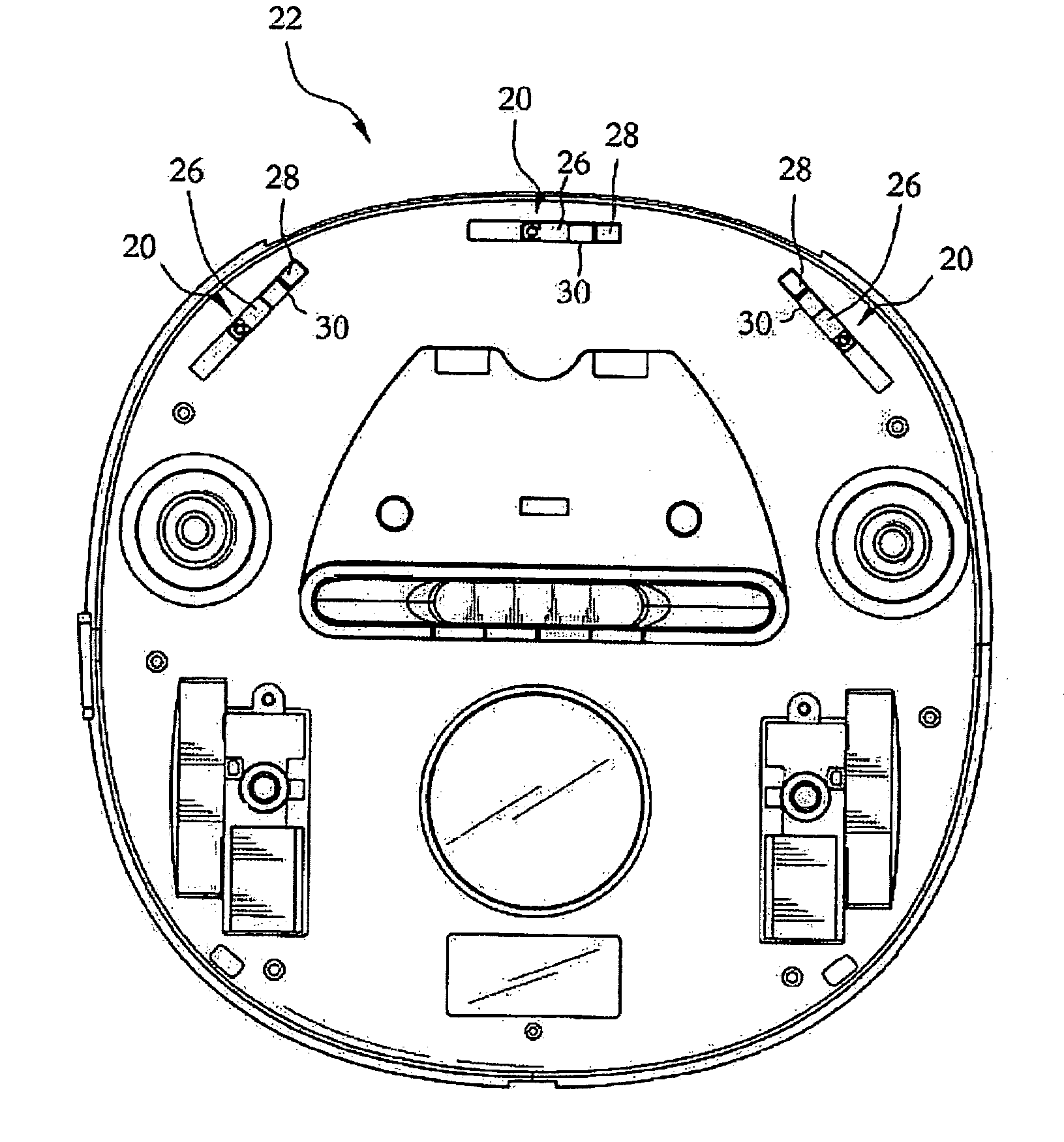
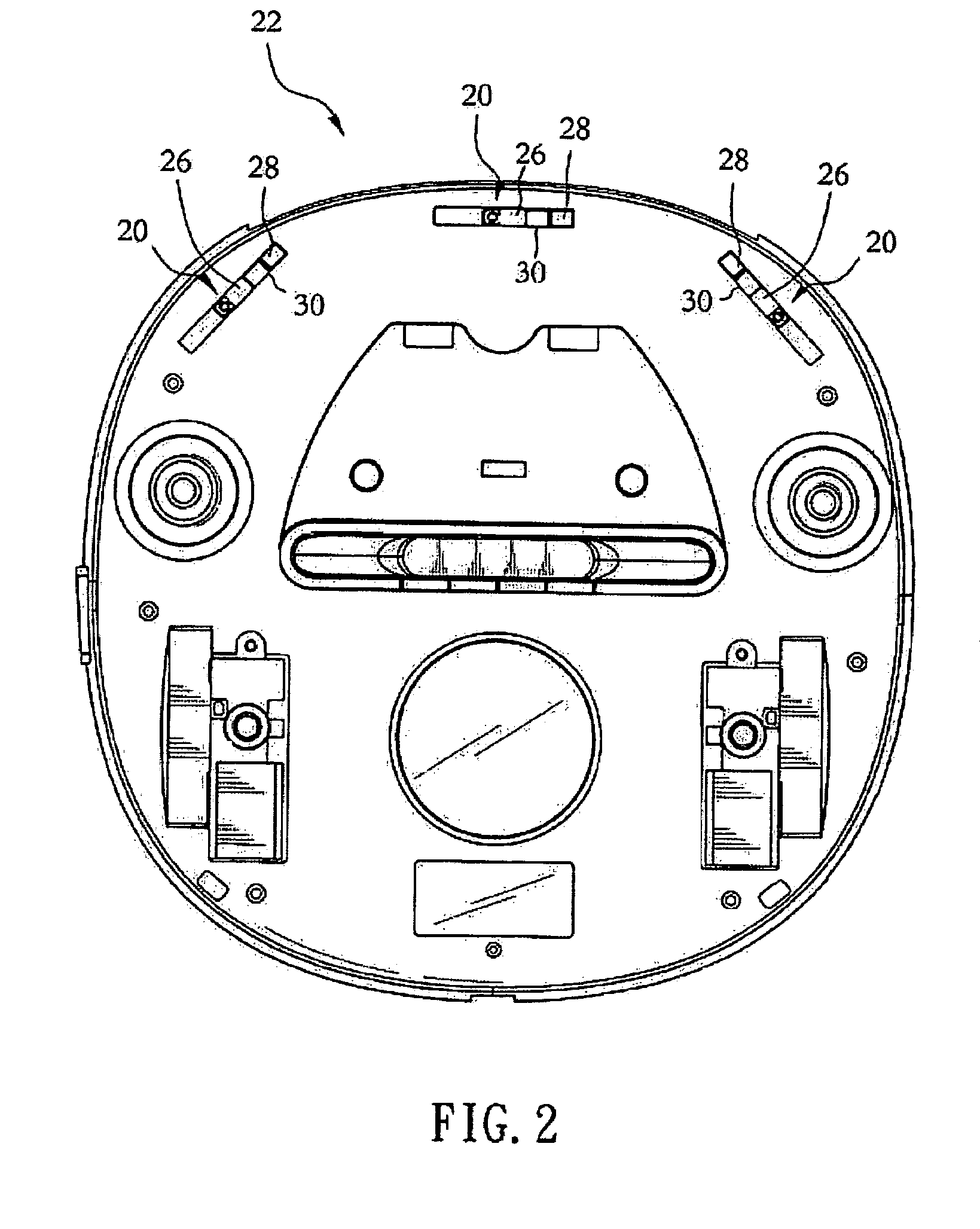
[0016]FIG. 2 is a vertical view showing that the infrared sensor of the present invention is adapted to the bottom of a vacuum cleaner; FIG. 3 is schematic view showing a preferred embodiment of the infrared sensor of the present invention; FIG. 6 is a sectional view of the infrared sensor of the present invention; and FIG. 7 is a perspective view of the infrared sensor of the present invention. The infrared sensor units 20 are disposed to the bottom of an automatic vacuum cleaner 22. The infrared rays are eradiated from a transmitter 201 disposed on each infrared sensor unit, then reflected by a ground 24, and picked up by a receiver 202 disposed on each infrared sensor unit to effectively measure the distance between the ground 24 and the automatic vacuum cleaner 22. Any instant change to the measurement will be immediately notified to the automatic vacuum cleaner 22 to stop advancing by giving a command to retreat or take a turn so as to prevent the automatic vacuum cleaner 22 fr...


PUM


Abstract

An infrared sensor at lower production cost for optimal massive production includes an infrared sensor unit disposed to the bottom of an automatic vacuum cleaner to measure the level of the ground to prevent the vacuum cleaner from turning overdue to any drop height created on the ground; a slide screen being disposed on the infrared sensor unit; and a small gateway to control the area for receiving energy of the infrared ray to precisely measure the drop height of the ground for the vacuum cleaner to automatically take turn whenever the drop height is detected to prevent a possible falling over.

Description

FIELD OF THE INVENTION[0001]The present invention relates to an infrared sensor, and more particularly to an improved infrared sensor that can be applied to all sorts of vacuum cleaner.BACKGROUND OF THE INVENTION[0002]The prior art illustrated in FIG. 1 is related to a U.S. Pat. No. 6,594,844B2. As illustrated, a measurement 1 is applied on an instrument at the bottom of the automatic vacuum cleaner to emit at a certain inclination through an infrared ray 10 to a ground 12; and another infrared ray 14 receives the reflection. Meanwhile, the distances respectively among the infrared ray 10, the infrared ray 14 and the ground 12 are measured from a first path 16 and a second path 18. Once the distances respectively among the first path 16, the second path 18 and the ground changes, it indicates that the distances respectively among the infrared ray 10, the infrared ray 14 and the ground 12 also change accordingly so as to notify the automatic vacuum cleaner to take turns to avoid fall...

Claims


Application Information

Patent Timeline
Patent Type & Authority Patents(United States)
IPC IPC(8): G01J5/00
CPCA47L9/009A47L2201/04
Inventor YAN, JASON
Owner HUNAN GRAND PRO ROBOT TECH
Why Eureka
Try Eureka