
Method and apparatus for reducing adjacent channel power in wireless communication systems

a wireless communication system and adjacent channel technology, applied in the direction of digital transmission, baseband system details, sustainable buildings, etc., can solve the problems of unacceptably high acp, the transfer characteristic of the amplifier is substantially different from linear, and the power of the adjacent channel is reduced by a factor of ten or more, so as to reduce the power of the adjacent channel, and achieve the effect of precision and efficient implementation of digital circuitry

Inactive Publication Date: 2008-08-05
RPX CORP +1
View PDF11 Cites 18 Cited by
  • Summary
  • Abstract
  • Description
  • Claims
  • Application Information

AI Technical Summary

Benefits of technology

[0025]A primary advantage of the present invention is that it provides an efficient and reliable alternative method to reduce adjacent channel power by adaptively and digitally pre-distorting the signal to compensate for the non-linearity of the amplifier.
[0026]Another advantage of the present invention is that the correction of the signal is performed on the digital base-band signal before it is converted to a radio frequency (RF) signal. In this way, the precision and efficient implementation of digital circuitry is utilized.

Problems solved by technology

These constraints are particularly severe for code division multiple access (CDMA) systems where the pseudo-random nature of the signal results in a peak power which exceeds the average power by a factor of ten or more.
Unfortunately, the transfer characteristic of the amplifier departs substantially from linear when in class AB mode.
This results in unacceptably high ACP.
The traditional method of linearizing the amplifier is to employ adaptive feed-forward which, while effective, results in a substantial cost increase.

Method used


Image

  • Method and apparatus for reducing adjacent channel power in wireless communication systems
  • Method and apparatus for reducing adjacent channel power in wireless communication systems
  • Method and apparatus for reducing adjacent channel power in wireless communication systems

Examples


Embodiment Construction

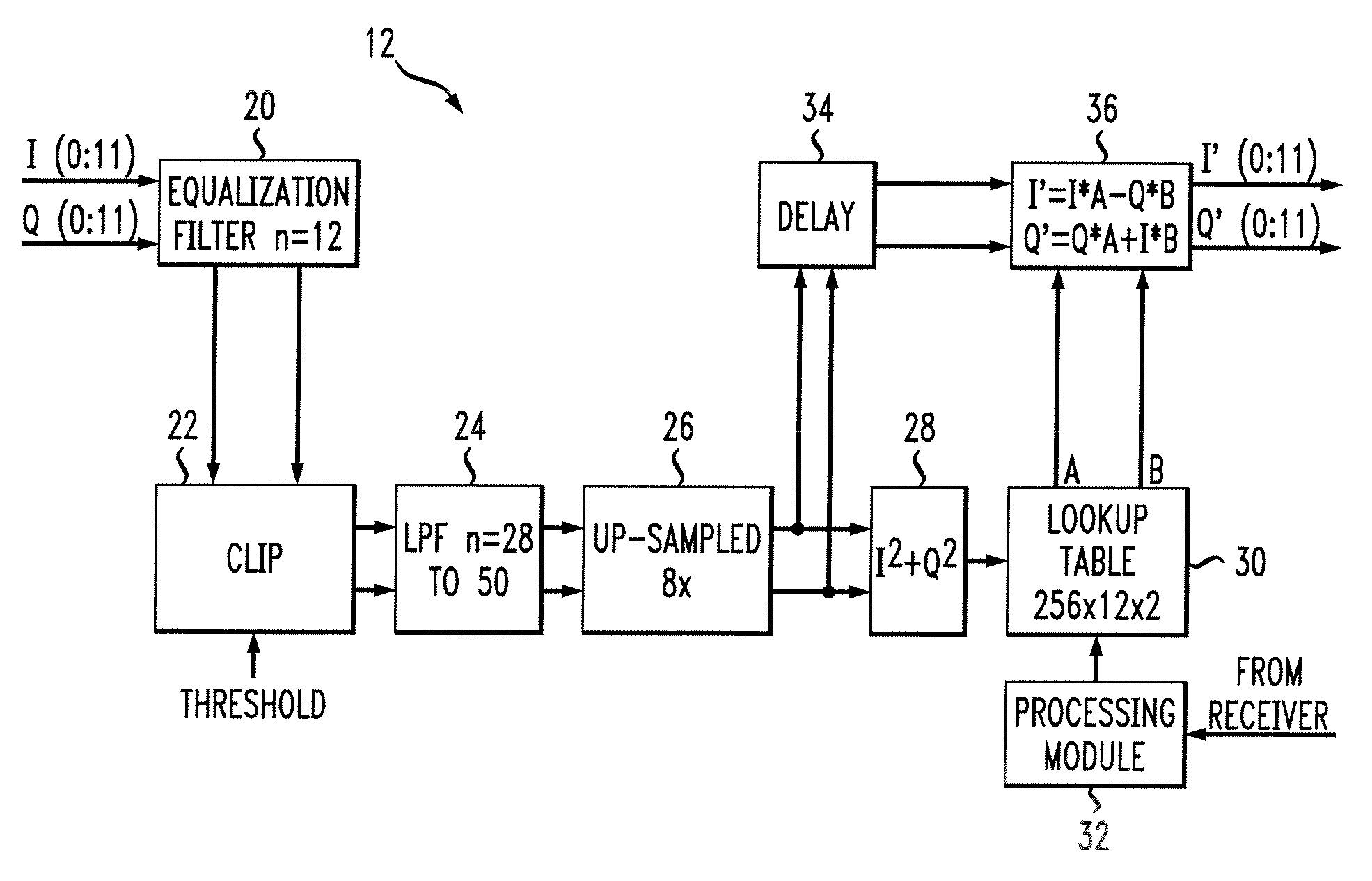
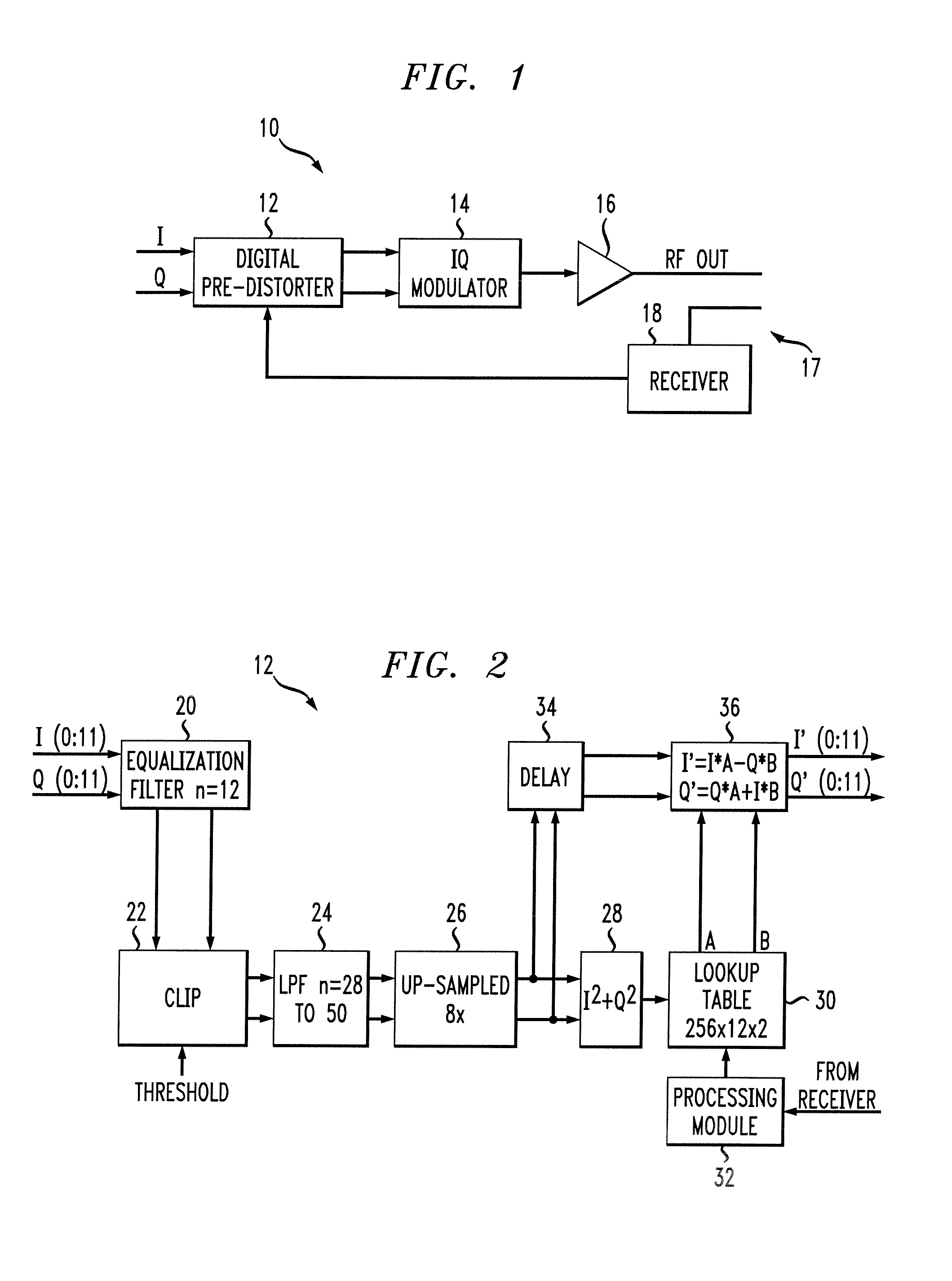
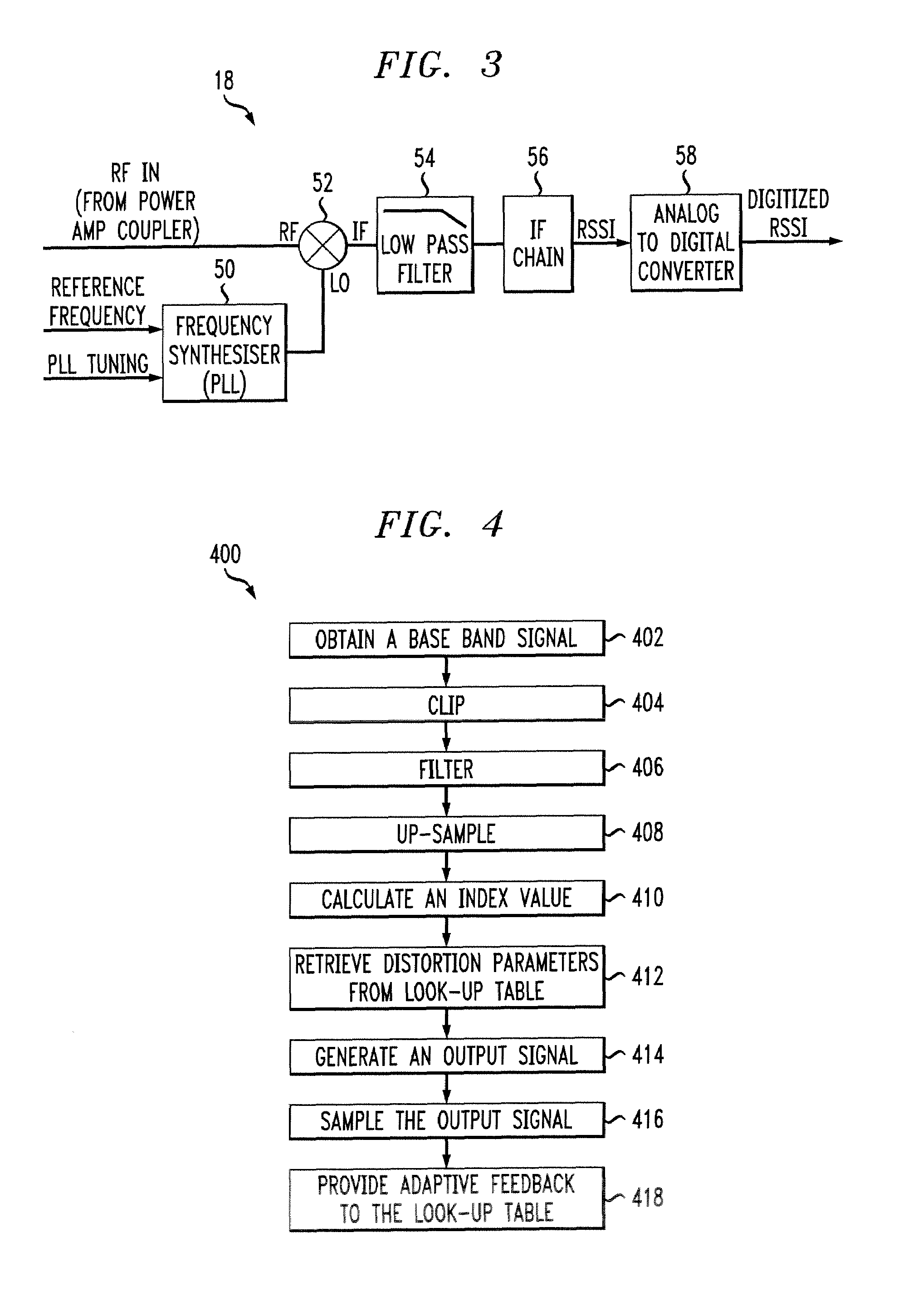
[0037]Referring now to the drawings wherein the showings are for purposes of illustrating particular embodiments of the invention only and not for purposes of limiting same, FIG. 1 provides a view of the overall system according to the present invention. As shown, the system 10 includes a digital pre-distorter, or pre-distorting module, 12 for receiving the input signal, an IQ modulator 14 connected to the output of the module 12, an amplifier 16 connected to the output of the modulator 14, and a receiver 18 that is coupled to the output of the amplifier through a coupler 17 and fed back to the module 12. These components are configured to apply a correction to a digital base-band signal (e.g. a code division multiple access (CDMA) signal, a wide band CDMA signal, a time division multiple access (TDMA) signal, an enhanced data rates through global system for mobile communications evolution (EDGE) signal, or any signal with a substantially large peak power to average power ratio) gen...


PUM


Abstract

This invention relates to a method and apparatus for reducing adjacent channel power in wireless communication systems. More particularly, the present invention is directed to a system for digitally and adaptively pre-distorting a signal that includes applying a correction to the signal before it is applied to the input of an amplifier such that the correction is equal and opposite to anticipated distortion produced by the amplifier. Thus, the correction and the amplifier distortion cancel one another resulting in a system with an overall linear transfer characteristic. In these circumstances, the adjacent channel power is desirably reduced.

Description

CROSS REFERENCE TO RELATED APPLICATION[0001]This application is related to U.S. application Ser. No. 09 / 396,829 entitled “Dynamic Path Gain Compensation for Radios in Wireless Communication Systems” filed on even date herewith on behalf of Miguel Dajer, Edward Ellis Eibling and Mark Y. McKinnon, now U.S. Pat. No. 6,507,732 (issued Jan. 14, 2003), which is hereby incorporated herein by this reference.BACKGROUND OF THE INVENTION[0002]This invention relates to a method and apparatus for reducing adjacent channel power in wireless communication systems. More particularly, the present invention is directed to a system for digitally and adaptively pre-distorting a signal that includes applying a correction to the signal before it is applied to the input of an amplifier such that the correction is equal and opposite to anticipated distortion produced by the amplifier. Thus, the correction and the amplifier distortion cancel one another resulting in a system with an overall linear transfer ...

Claims


Application Information

Patent Timeline
IPC IPC(8): H04L25/49H04B1/04H04B1/62H04L27/36
CPCH04B1/62H04L27/368Y02B60/50H04B1/7097
Inventor JOHNSON, ROBERT EVERESTLENEY, MARK THOMASVELLA-COLEIRO, GEORGE PHILIP
Owner RPX CORP
Learn More