

Optical signal demodulator
a technology of optical fiber communication and demodulator, which is applied in the direction of multiplex communication, optical elements, instruments, etc., can solve the problems of optical fiber delay of optical signal transmitted from the mach-zehnder interferometer, and difficulty in ensuring the reproducibility of the /4-phase shift process on a dqpsk optical signal
- Summary
- Abstract
- Description
- Claims
- Application Information
AI Technical Summary
Benefits of technology
Problems solved by technology
Method used
Image

Examples
first embodiment
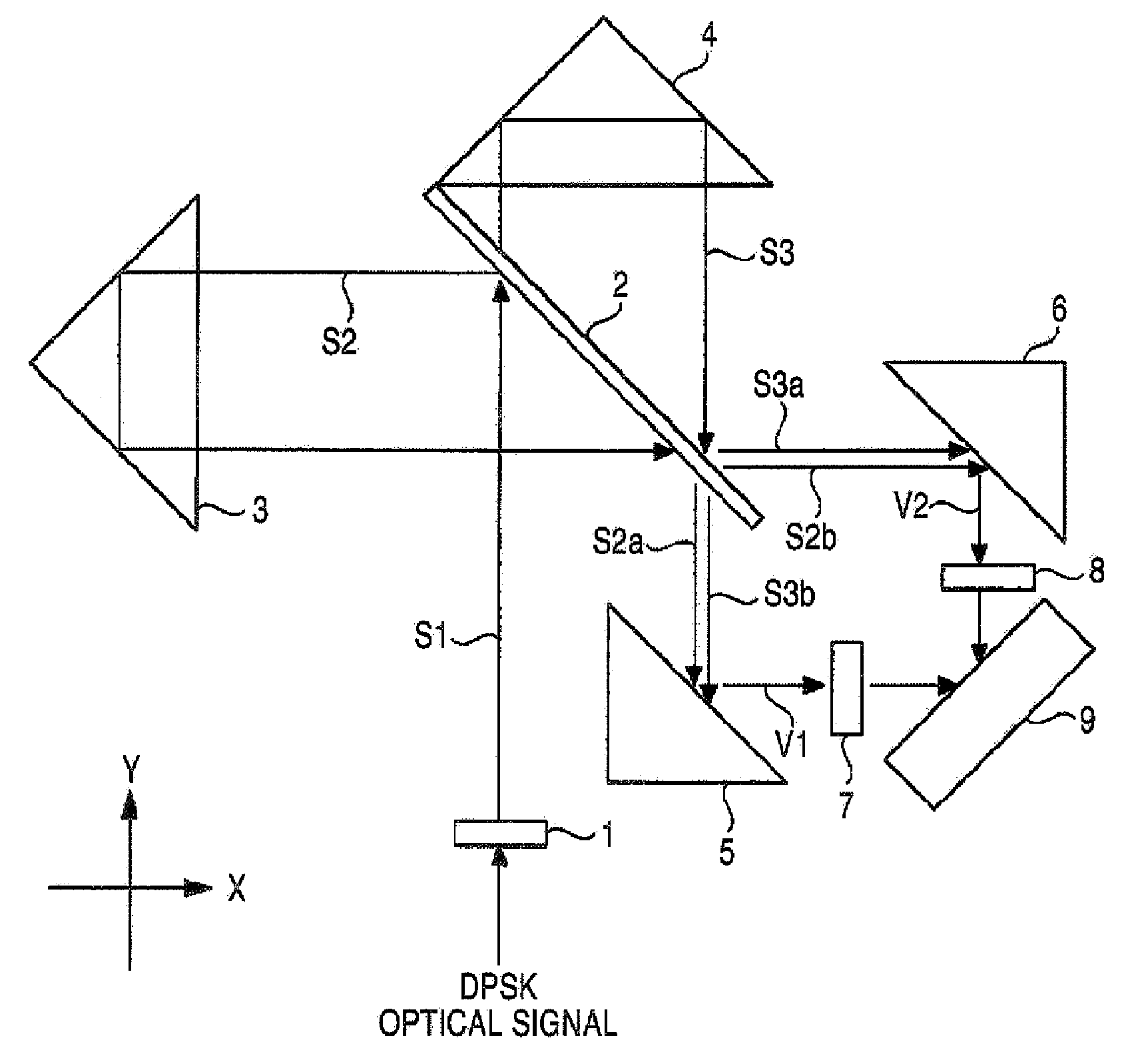
[0081]Hereinafter, a first embodiment of the invention will be described with reference to the accompanying drawings. FIG. 1 is a diagram schematically showing the configuration of a demodulator of the first embodiment. The demodulator of the first embodiment demodulates a DPSK-modulated optical signal (DPSK optical signal).
[0082]As shown in the figure, the demodulator of the first embodiment is configured by a first lens 1, a half mirror 2, a first reflector 3, a second reflector 4, a first mirror 5, a second mirror 6, a second lens 7, a third lens 8, and an balanced optical detector 9. Among the constituent components, the first lens 1, the half-mirror 2, the first reflector 3, the second reflector 4, the first mirror 5, the second mirror 6, the second lens 7, and the third lens 8 constitute a Michelson interferometer.
[0083]The first lens 1 is, for example, a collimator lens, coverts a DPSK optical signal which is incident from an optical fiber (not shown) into parallel light S1, ...
second embodiment
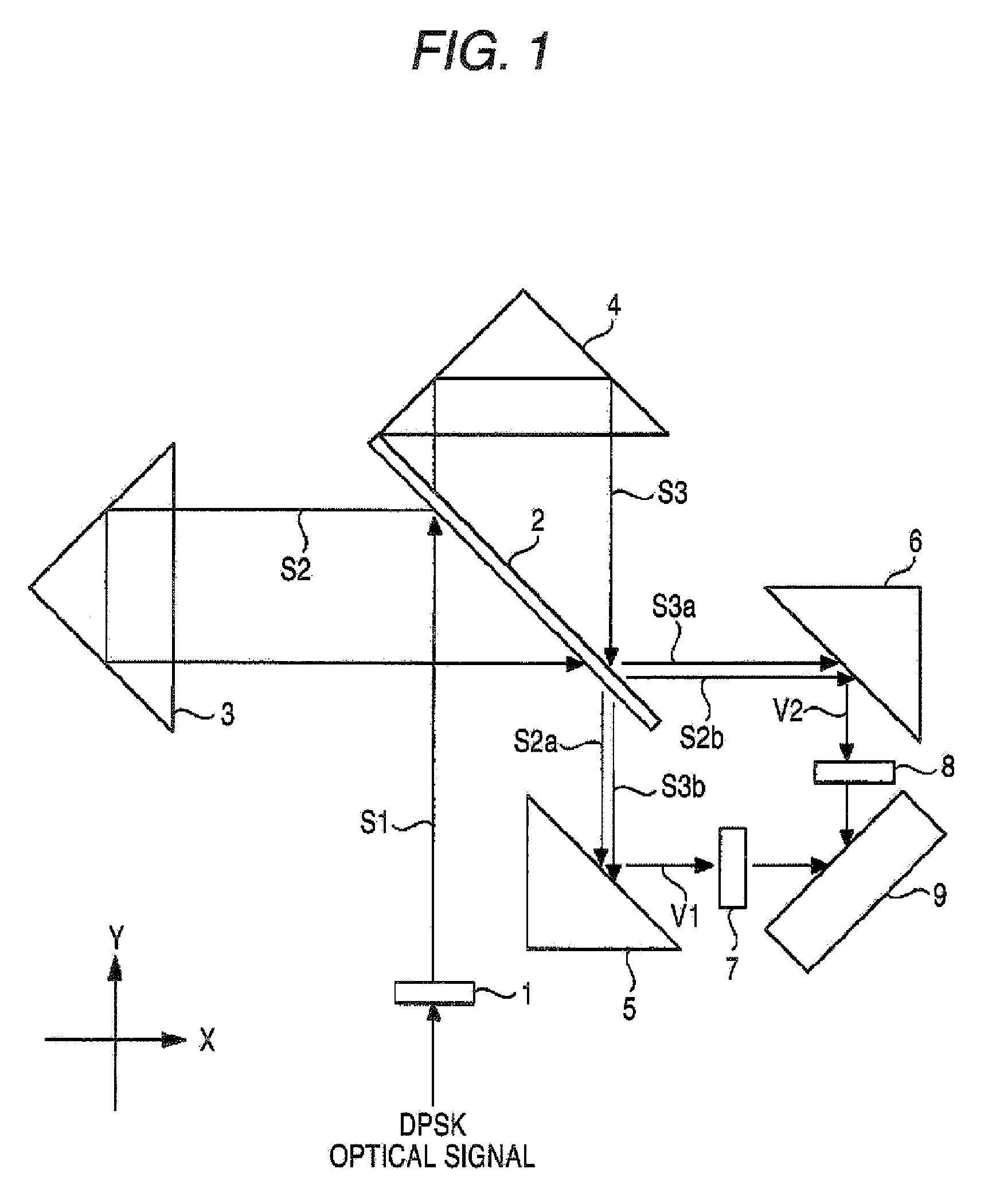
[0100]Next, a second embodiment of the invention will be described with reference to FIG. 2. FIG. 2 is a diagram schematically showing the configuration of a demodulator of the second embodiment. The demodulator of the second embodiment demodulates a DQPSK-modulated optical signal (DQPSK optical signal).
[0101]As shown in the figure, the demodulator of the second embodiment is configured by a first lens 10, a two-split prism 11, a half-mirror 12, a first reflector 13, a phase adjusting section 14, a second reflector 15, a first mirror 16, a second mirror 17, a second lens 18, a third lens 19, a fourth lens 20, a fifth lens 21, a first balanced optical detector 22, and a second balanced optical detector 23.
[0102]The first lens 10 is, for example, a collimator lens, coverts a DQPSK optical signal which is incident from an optical fiber (not shown) into parallel light S10, and emits the parallel light to the two-split prism 11 disposed on the emission axis (Y-axis). The two-split prism ...
third embodiment
[0130]Next, a third embodiment of the invention will be described with reference to FIG. 3. FIG. 3 is a diagram schematically showing the configuration of a demodulator of the third embodiment. The demodulator of the third embodiment demodulates a DQPSK-modulated optical signal (DQPSK optical signal).
[0131]As shown in the figure, the demodulator of the third embodiment is configured by a first lens 30, a half-mirror 31, a first reflector 32, a second reflector 33, a phase adjusting section 34, a first mirror 35, a second mirror 36, a second lens 37, a third lens 38, a fourth lens 39, a fifth lens 40, a first balanced optical detector 41, and a second balanced optical detector 42.
[0132]The first lens 30 is, for example, a collimator lens, coverts a DQPSK optical signal which is incident from an optical fiber (not shown) into parallel light S20, and emits the parallel light to the half-mirror 31 disposed on the emission axis (X-axis). The half-mirror 31 reflects the parallel light S20...
PUM
| Property | Measurement | Unit |
|---|---|---|
| optical path length | aaaaa | aaaaa |
| delay time | aaaaa | aaaaa |
| refractive indices | aaaaa | aaaaa |
Abstract
Description
Claims
Application Information