Image detection method and image detecting apparatus

a detection method and image technology, applied in the direction of instruments, static indicating devices, lenses, etc., can solve the problems of inability to resolve structures smaller than the diffraction limit by optical systems, and inability to achieve favorable image formation performance. to achieve the effect of enhancing evanescent waves

Inactive Publication Date: 2008-08-12
OLYMPUS CORP
View PDF5 Cites 40 Cited by
  • Summary
  • Abstract
  • Description
  • Claims
  • Application Information

AI Technical Summary

Benefits of technology

[0044]The present invention is made in view of the abovementioned circumstances, and an object of the present invention is to provide an image detection method in which an effect of a resonant enhancement of evanescent waves is reduced in an optical system including an optical element formed of a material exhibiting negative refraction.

Problems solved by technology

Moreover, a structure smaller than the diffraction limit can not be resolved by an optical system.
Due to such resonant enhancement, a favorable image formation performance cannot be achieved.
Therefore, a structure which is smaller than the spatial frequency equivalent to the resolution limit cannot be resolved.
Moreover, in optical systems including an optical element which is formed by a material exhibiting negative refraction, since the resonant enhancement of the evanescent waves described above inhibits an image formation of a low frequency component carried by the propagating light, in addition to the smaller structure than the spatial frequency equivalent to the resolution limit, it is all the more damaging.

Method used


Image

  • Image detection method and image detecting apparatus
  • Image detection method and image detecting apparatus
  • Image detection method and image detecting apparatus

Examples


first embodiment

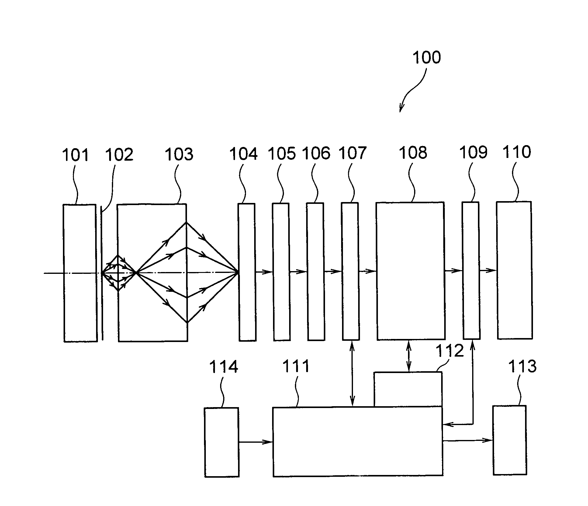
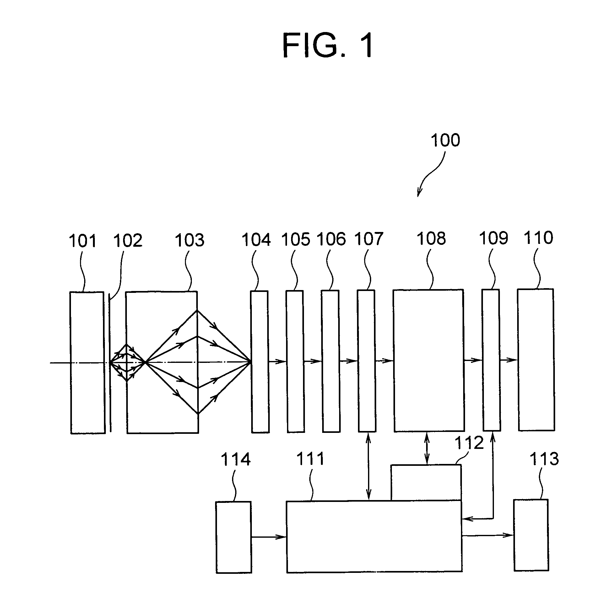
[0067]FIG. 1 shows a schematic structure of an image detecting apparatus 100 according to the present invention. A sample 102 is fixed on a sample stage 101. The sample 102 corresponds to an object plane. Light from the sample 102 is incident on a negative refraction lens 103.

[0068]The negative refraction lens 103 is formed by a flat plate made of a material exhibiting negative refraction. As it has been mentioned above, apart from photonic crystals mentioned above, materials such as metallic thin films, chiral substances, photonic crystals, metamaterials, left-handed materials, backward wave materials, and negative phase velocity media (materials) can be used as the material exhibiting negative refraction. The light from the sample 102 is passed through the negative refraction lens 103, and is transferred optically to a detection plane of an imaging device 104. This corresponds to a step of transferring image information. Moreover, a CCD (charge coupled device) can be used as the i...

modified embodiment

[0113]The effect of the present invention is not restricted to a case in which the transfer function of the optical system exhibits the resonant enhancement in the specific spatial frequency region. FIG. 8 shows a transfer function in a case in which there is no resonant enhancement of the transfer function in the specific spatial frequency region.

[0114]It shows that the transfer function starts decreasing from a region in which a value of a wave number κ which is normalized is above 3, and minute information of about ⅓ of the wavelength can be transmitted.

[0115]A detailed computing process is not shown here. However, it is evident that by performing exactly the same calculation mentioned above in the same order, it is possible to restore an image closer to the original image, from the image detected at the image plane. In this case, due to an accuracy of transfer function data shown in FIG. 8, and the discrete interval of the numerical integral, sometimes the restoring capacity is ...

second embodiment

[0120]Next, an image detection method according to a second embodiment of the present invention will be described below. In the second embodiment, the compensation processing is performed by using a calculation different from the calculation in the first embodiment. Similarly as in the first embodiment, a complex amplitude distribution f(ξ) of an image detected on the image plane and the Fourier transform F(κ) thereof are defined as in the following equation (16) and equation (17).

ƒ(ξ)=∫−∞∞F(κ)exp(2πiκξ)dκ=FT−1{F(κ)}  equation (16)

F(κ)=∫−∞∞ƒ(ξ)exp(−2πiκξ)dξ=FT{ƒ(ξ)}  equation (17)

[0121]FT and FT−1 in equation (16) and equation (17) are terms by which the Fourier transform and a reverse Fourier transform are expressed by symbols. Moreover, for the transfer function |τ(κ)| from the object plane to the image plane via the negative refraction lens, a reciprocal 1 / |τ(κ)| and the function f(ξ) are let to be the Fourier transform mutually.

[0122]In other words, the following equation (18) a...


PUM


Abstract

An image detection method includes steps of transferring image information in which, information of an object image on a sample (object plane) is transferred to a detection plane (image plane) of an imaging element via an optical system which includes a negative refraction lens formed of a material exhibiting negative refraction, detecting image in which, image-plane image information transferred to the detection plane (image plane) of the imaging device is detected optically, and calculation processing in which, for the image-plane image information which is detected, information of the object image is calculated by performing a calculation processing based on optical characteristics of the optical system.

Description

CROSS-REFERENCE TO RELATED APPLICATION[0001]The present application is based upon and claims the benefit of priority from the prior Japanese Patent Application No. 2006-012424 filed on Jan. 20, 2006; the entire contents of which are incorporated herein by reference.BACKGROUND OF THE INVENTION[0002]1. Field of the Invention[0003]The present invention relates to a method of detecting an image by using an imaging optical system such as a microscope, a camera, and an endoscope, and an apparatus which detects an image by using an imaging optical system such as a microscope, a camera, and an endoscope.[0004]2. Description of the Related Art[0005]In recent years, resolution of an image detecting apparatus in which an imaging optical system such as a microscope, a camera, and an endoscope is used has been improved. Particularly, in a field of microscopes and optical recording, an almost no aberration optical system has been realized, and a resolution as an imaging optical system has been co...

Claims


Application Information

Patent Timeline
Patent Type & Authority Patents(United States)
IPC IPC(8): G02B1/00G02B15/14G02B9/00G06K9/32G09G5/00
CPCB82Y20/00G02B1/005G02B23/2423G02B13/24G02B21/02G02B1/007
Inventor TSUKAGOSHI, TAKUYA
Owner OLYMPUS CORP
Why Eureka
Try Eureka