Image detection method and image detecting apparatus
a detection method and image technology, applied in the direction of instruments, static indicating devices, lenses, etc., can solve the problems of inability to resolve structures smaller than the diffraction limit by optical systems, and inability to achieve favorable image formation performance. to achieve the effect of enhancing evanescent waves
- Summary
- Abstract
- Description
- Claims
- Application Information
AI Technical Summary
Benefits of technology
Problems solved by technology
Method used
Image
Examples
first embodiment
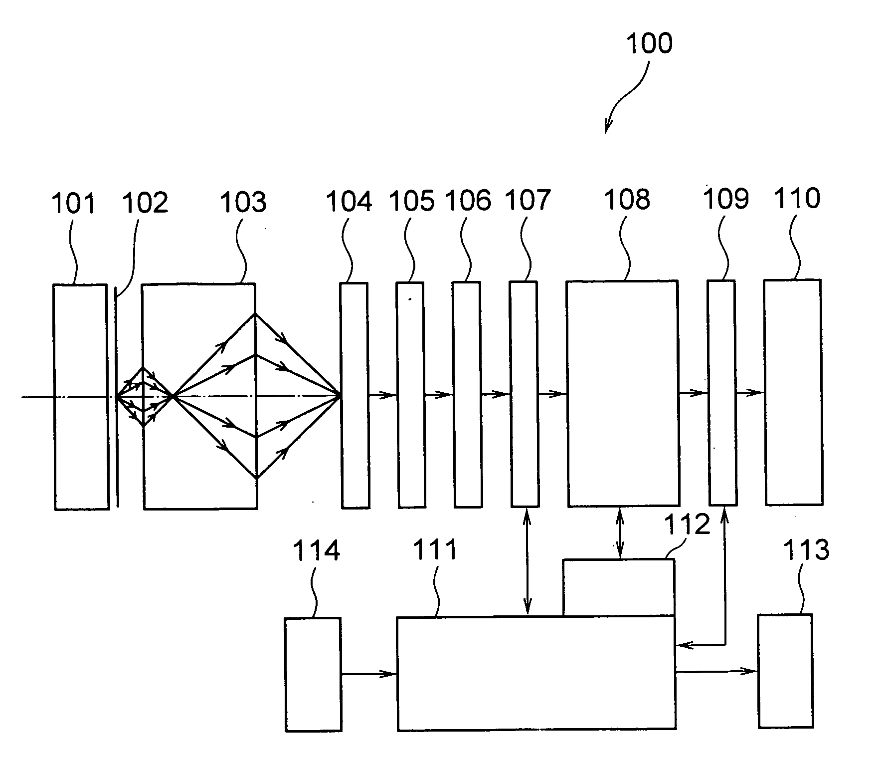
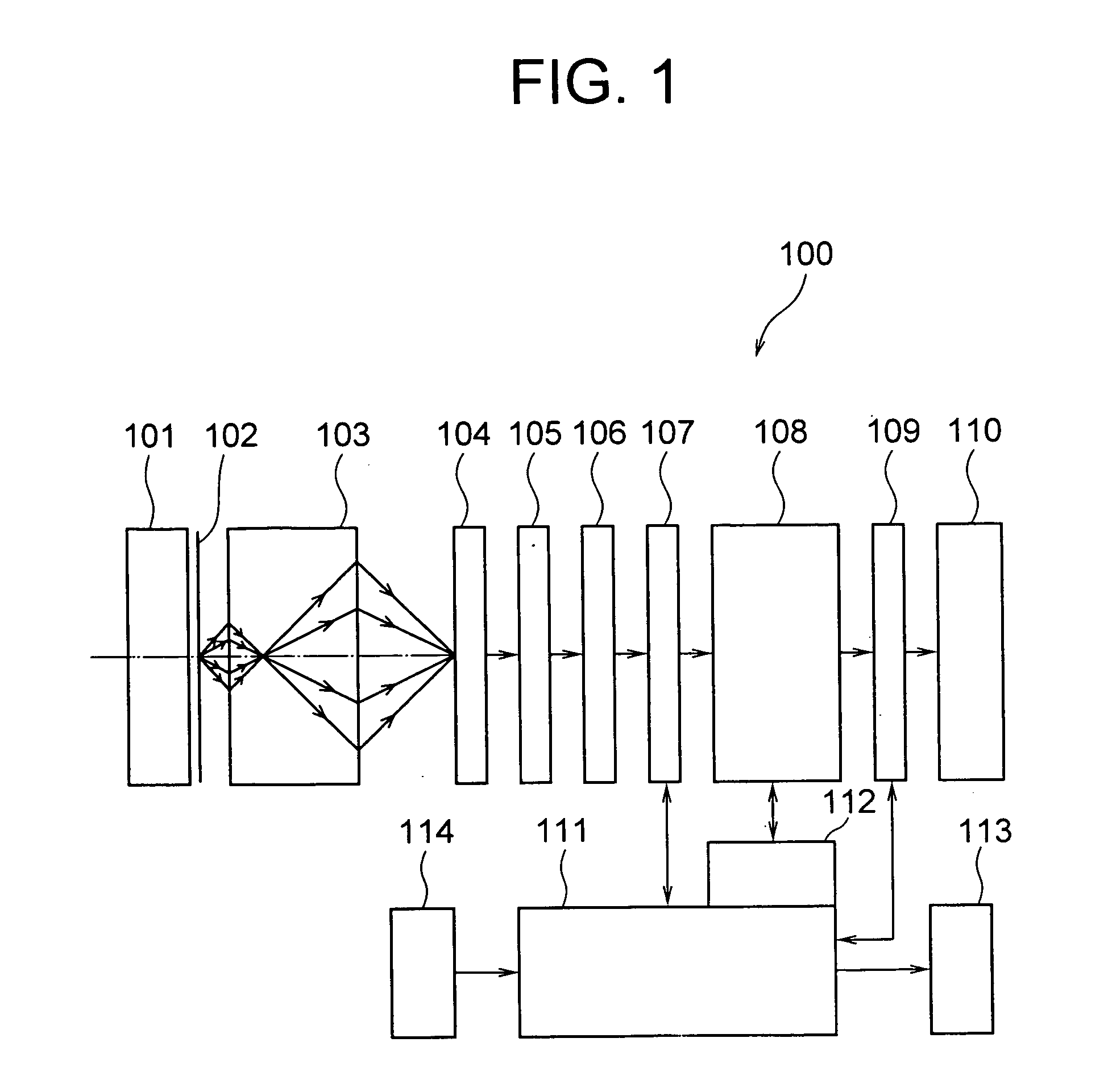
[0066]FIG. 1 shows a schematic structure of an image detecting apparatus 100 according to the present invention. A sample 102 is fixed on a sample stage 101. The sample 102 corresponds to an object plane. Light from the sample 102 is incident on a negative refraction lens 103.
[0067]The negative refraction lens 103 is formed by a flat plate made of a material exhibiting negative refraction. As it has been mentioned above, apart from photonic crystals mentioned above, materials such as metallic thin films, chiral substances, photonic crystals, metamaterials, left-handed materials, backward wave materials, and negative phase velocity media (materials) can be used as the material exhibiting negative refraction. The light from the sample 102 is passed through the negative refraction lens 103, and is transferred optically to a detection plane of an imaging device 104. This corresponds to a step of transferring image information. Moreover, a CCD (charge coupled device) can be used as the i...
modified embodiment
[0105]The effect of the present invention is not restricted to a case in which the transfer function of the optical system exhibits the resonant enhancement in the specific spatial frequency region. FIG. 8 shows a transfer function in a case in which there is no resonant enhancement of the transfer function in the specific spatial frequency region.
[0106]It shows that the transfer function starts decreasing from a region in which a value of a wave number κ which is normalized is above 3, and minute information of about ⅓ of the wavelength can be transmitted.
[0107]A detailed computing process is not shown here. However, it is evident that by performing exactly the same calculation mentioned above in the same order, it is possible to restore an image closer to the original image, from the image detected at the image plane. In this case, due to an accuracy of transfer function data shown in FIG. 8, and the discrete interval of the numerical integral, sometimes the restoring capacity is ...
second embodiment
[0112]Next, an image detection method according to a second embodiment of the present invention will be described below. In the second embodiment, the compensation processing is performed by using a calculation different from the calculation in the first embodiment. Similarly as in the first embodiment, a complex amplitude distribution f(ξ) of an image detected on the image plane and the Fourier transform F(κ) thereof are defined as in the following equation (16) and equation (17).
f(ξ)=∫−∞0F(κ)exp(2πiκξ)dκ=FT−1{F(κ)} equation (16)
F(κ)=∫−∞0f(ξ)exp(−2πiκξ)dξ=FT{f(ξ)} equation (17)
FT and FT−1 in equation (16) and equation (17) are terms by which the Fourier transform and a reverse Fourier transform are expressed by symbols. Moreover, for the transfer function |τ(κ)| from the object plane to the image plane via the negative refraction lens, a reciprocal 1 / |τ(κ)| and the function f(ξ) are let to be the Fourier transform mutually.
[0113]In other words, the following equation (18) and equ...
PUM
 Abstract
Description
Claims
Application Information
 - R&D
- Intellectual Property
- Life Sciences
- Materials
- Tech Scout
- Unparalleled Data Quality
- Higher Quality Content
- 60% Fewer Hallucinations
Browse by: Latest US Patents, China's latest patents, Technical Efficacy Thesaurus, Application Domain, Technology Topic, Popular Technical Reports.
© 2025 PatSnap. All rights reserved.Legal|Privacy policy|Modern Slavery Act Transparency Statement|Sitemap|About US| Contact US: help@patsnap.com


