Supercharge Your Innovation With Domain-Expert AI Agents!

Mechanically Q-switched CO2 laser

a laser and mechanical technology, applied in the direction of laser details, optical resonator shape and construction, laser details, etc., can solve the problems of difficult growth, high cost of e-o cdte crystals, and high cost of cdte e-o switch, and achieve the effect of high pulse ra

Inactive Publication Date: 2008-08-12
COHERENT INC
View PDF13 Cites 5 Cited by
  • Summary
  • Abstract
  • Description
  • Claims
  • Application Information

AI Technical Summary

Benefits of technology

This approach enables the CO2 laser to achieve high PRFs, such as 100 KHz, while maintaining efficient output power and mode quality, comparable to conventional Q-switched lasers, without the cost and complexity of cadmium telluride switches, making it suitable for material processing applications.

Problems solved by technology

The cost of a CdTe E-O switch is relatively high and can represent between about 25% and 30% of the total cost of a Q-switched CO2 laser.
The E-O CdTe crystals are expensive, difficult to grow, difficult to polish and there are few suppliers thereof worldwide.
This circuitry is expensive and difficult to design.
Such components, and indeed the CdTe crystal, introduce significant optical losses within the laser resonant cavity.
The fast rotational speed required a high degree of mechanical balancing for the rotating mirrors which added appreciable cost to the Q-switch laser.
These early mechanical Q-switching techniques were, and are still not suitable for the above-discussed material processing applications.
Although there has been an awareness of these early mechanical Q-switching experiments, mechanical Q-switching is not included in any commercially available gas or solid-state laser.

Method used


Image

  • Mechanically Q-switched CO2 laser
  • Mechanically Q-switched CO2 laser
  • Mechanically Q-switched CO2 laser

Examples


Embodiment Construction

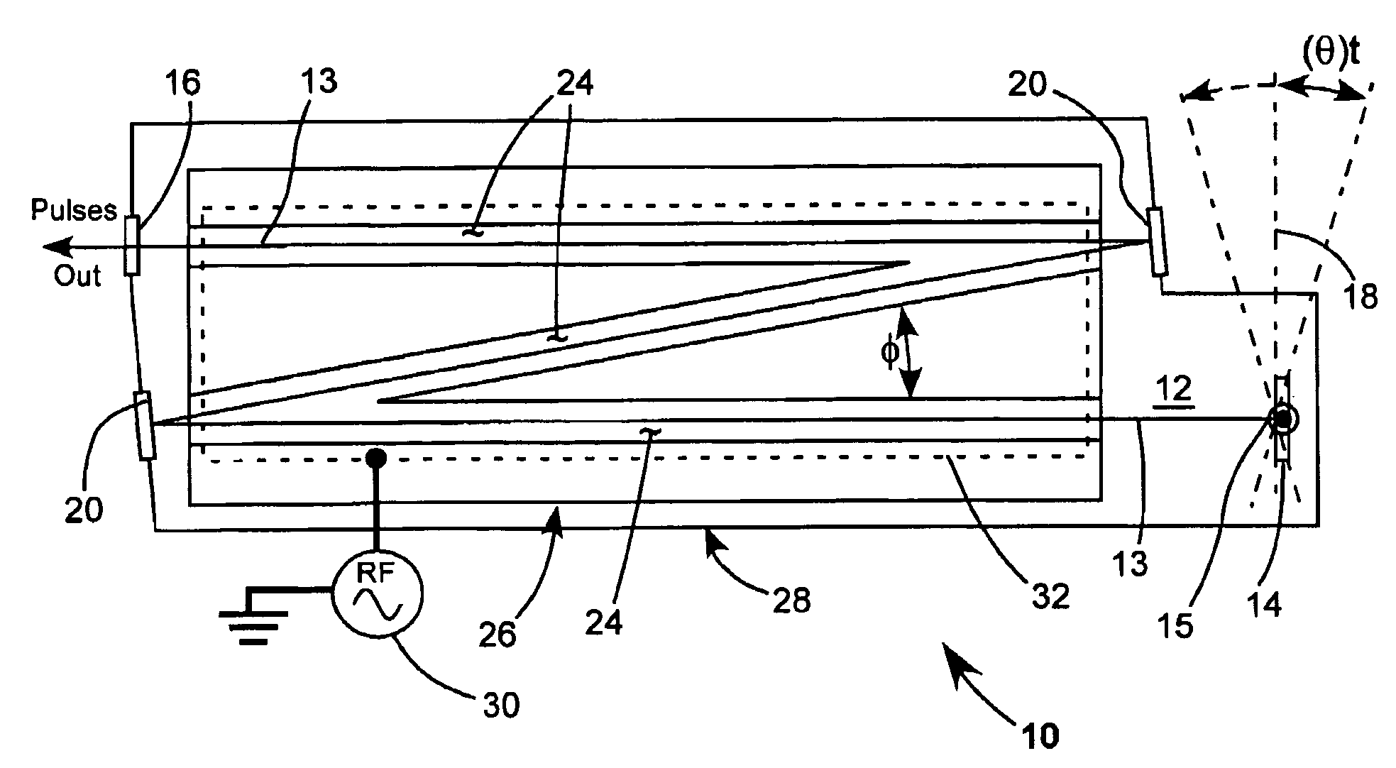
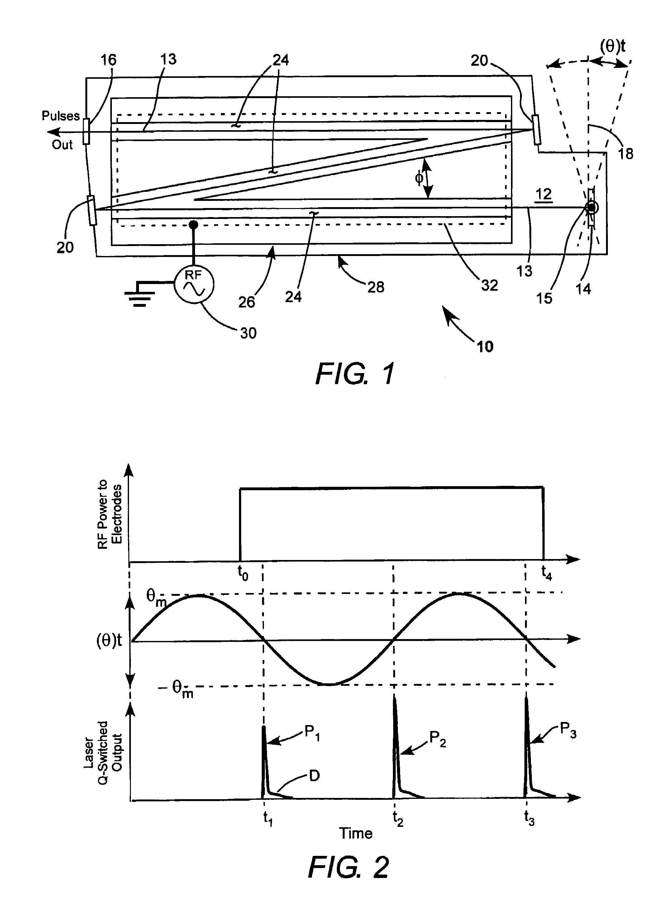
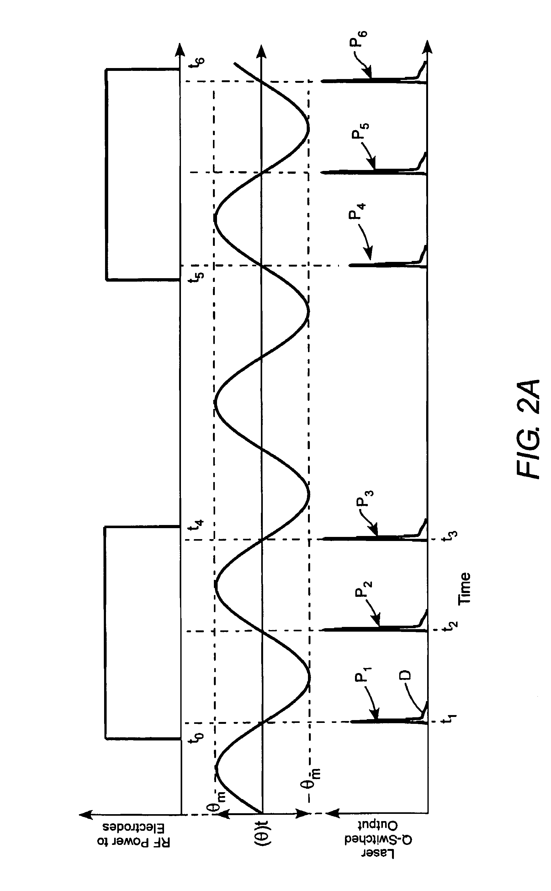
[0024]Referring now to the drawings, wherein like components are designated by like reference numerals, FIG. 1 illustrates a preferred embodiment of a Q-switched pulsed CO2 laser 10 in accordance with the present invention. FIG. 2 is a timing diagram graphically depicting operation characteristics of the laser.

[0025]Laser 10 includes a housing 28 filled with a lasing gas mixture including CO2 and at least one inert gas. One preferred gas mixture is a CO2:nitrogen (N2):helium (He) gas mixture at about 80 to 100 Torr pressure. A laser resonator 12 is terminated by a fixed mirror 16, sealed to the housing, and a mirror 14, here, within the housing. Mirror 14 is periodically tiltable (oscillatable), about an axis 15 perpendicular to the longitudinal resonator axis 13, through angles ±θm on opposite sides of an optimum alignment plane 18, perpendicular to a longitudinal axis of the resonator. Locating mirror 14 within the resonator is preferred as far as minimizing optical losses is conc...


PUM


Abstract

A CO2 laser has a resonator mirror that oscillates about an axis perpendicular to the resonator axis through an angular range of oscillation sufficient that the resonator is only able to deliver radiation for a fraction of an oscillation period of the mirror. In one example of the laser, the oscillating mirror is an end-mirror of the resonator. In another example, the oscillating mirror is a fold mirror of the resonator.

Description

TECHNICAL FIELD OF THE INVENTION[0001]The present invention relates in general to Q-switched pulsed lasers. The invention relates in particular to Q-switched pulsed carbon dioxide (CO2) lasers.DISCUSSION OF BACKGROUND ART[0002]CO2 lasers typically deliver radiation having a wavelength between about 9 and 111 micrometers (μm), with 10.6 μm, for which gain is highest, being a common output wavelength. Wavelengths in this range are strongly absorbed by materials including ceramics, glasses, plastics, wood, paints, and paper. This makes a CO2 a preferred laser for material processing applications involving these materials. Such applications include marking and drilling.[0003]Many of these material processing applications require pulsed CO2 lasers having relatively high peak pulse powers, for example, 1 kilowatt (KW) or greater at relatively low average powers, for example, 50 Watts (W) or less. High pulse repetition frequencies (PRF), for example, between about a 10 kilohertz (KHz) and ...

Claims


Application Information

Patent Timeline
Patent Type & Authority Patents(United States)
IPC IPC(8): H01S3/22H01S3/08
CPCH01S3/2232H01S3/123H01S3/076H01S3/0805H01S3/0813H01S3/097H01S3/0816
Inventor SPINELLI, LUIS A.DEMARIA, ANTHONY J.SEGUIN, VERNON
Owner COHERENT INC
Features
  • R&D
  • Intellectual Property
  • Life Sciences
  • Materials
  • Tech Scout
  • Unparalleled Data Quality
  • Higher Quality Content
  • 60% Fewer Hallucinations
Learn More