Efficient finder patterns and methods for application to 2D machine vision problems

a machine vision and efficient technology, applied in the field offinder patterns, can solve the problems of poor data density, additional algorithmic complexity, and limited data amount of one-dimensional barcodes, and achieve the effects of low surface area use, easy location, and direct correction of perspectiv

Inactive Publication Date: 2008-08-12
NEXTCODE CORP
View PDF48 Cites 46 Cited by
  • Summary
  • Abstract
  • Description
  • Claims
  • Application Information

AI Technical Summary

Benefits of technology

[0020]An advantage of the invention is to provide a small, visually unobtrusive, and computationally efficient finder pattern which is easily located in images of targets containing significant blur, shadow, rotation, perspective distortion, and arbitrary nearby graphic elements.
[0021]Another advantage of the invention is to easily allow simple, direct correction of perspective. distortion in images by calculation of a coordinate mapping between the real-word target and an image of the target using location information of the finder pattern elements. This obviates the need for secondary timing patterns to determine surface metrics, and results in minimal surface area use for finder pattern elements.
[0022]Another advantage of the invention is to provide a single finder pattern strategy which can support simultaneous search for a variety of codes with different target shapes and sizes by using a single finder pattern recognition algorithm with a series of one or more externally maintainable finder pattern specifications.

Problems solved by technology

Additionally, one dimensional barcodes are very limited in the amount of data they can carry, and have poor data density.
Such distortion causes a number of problems for processing logic used to identify and locate the finder patterns.
Accordingly, additional algorithmic complexity is required to compensate for the perspective distortions.
Although the mathematics of perspective has been well understood for centuries, finder patterns for barcodes have not been designed to easily facilitate correction for this distortion.
However, if the QR target is rotated, so that laser scan lines are not perfectly aligned with the rectangular edges of the code, (or equivalently, so that a line of image pixels in a digital camera is not perfectly aligned with the rectangular edges of the code in that image), or if the plane of the target is tilted with respect to the optical axis, then the effectiveness of the finder method substantially decreases.
This added complexity and process steps are disadvantageous.
Most conventional finder patterns are effective under good focus conditions, but rapidly degrade in the presence of blur.
Other common issues like sensor noise, shadows, and lighting gradients, also affect the feature point location estimates.
Thus, the long edges may not be recognized, or they may not be recognized for their full length and significant error can be introduced into the estimated location and orientation.
Long straight line finder patterns which are common in one dimensional codes do not work very well generally with 2D codes.
This is required because the perspective distortion cannot be determined from knowledge of the location and orientation of only two lines.
Determining the location and orientation of lines of alternating light and dark modules, especially under blur and shadow conditions, requires a time consuming computational process that typically has poor error characteristics.
Data Matrix thus has a poorly designed finder pattern for use in conditions where perspective, blur, and other distortions are likely.
Moreover, the timing patterns require a substantial percentage of the available space, thereby limiting the overall data density of the code.
They cope poorly with common problems like perspective and blur, and they typically occupy a significant percentage of the target object code area.
Accordingly, the finder patterns are aesthetically objectionable to graphic artists because they tend to clash with product artwork and / or detract from the overall appearance of product packaging.
These finder patterns make it difficult to introduce consumer friendly branding or colorful graphic information, e.g., icons, calling attention to intended use or data content.
The visual dominance of finder patterns can detract from and limit the effectiveness of iconic information elsewhere on the target.
Clearly, they are not appropriate for other related applications such as assisting in machine recognition of symbols, logos, artwork, and general objects in the real-world.
Artistic graphic packaging elements can cause significant technical problems for a decoder by introducing structures that will confuse finder algorithms.
Accordingly, the finder patterns must typically occur in specific locations, e.g., outside or protruding from the outside, or at the corners of the code, thereby, introducing limitations in the overall shape of codes and in the range of code sizes that are available or practical.
In additional, the conventional finder patterns typically do not work well on non-linear geometries, e.g., a curved enclosure outline or an outline with concave portions.

Method used


Image

  • Efficient finder patterns and methods for application to 2D machine vision problems
  • Efficient finder patterns and methods for application to 2D machine vision problems
  • Efficient finder patterns and methods for application to 2D machine vision problems

Examples


Embodiment Construction

[0041]In a typical application of this invention, an image is captured by a camera device of some two dimensional (planar or near-planar) object. In the preferred embodiment, a camera is an ordinary optical sensor device that produces an array of digital information in the memory of some computational device. It should be obvious that any sensing device capable of producing a two dimensional image, such as a range sensor, short range radar, document scanner or other apparatus can also be a suitable “camera”.

[0042]A target object may be something as simple as a pattern of information printed in black ink on white paper (like the machine readable codes discussed earlier) that is sensed via ambient light by the camera. Alternatively it may be a complex pattern of colors or variations in the target surface such as a texture or deliberate deformations like Braille illuminated by light, sound, or other form of radiation from a specialized source with specific characteristics. It is also p...


PUM


Abstract

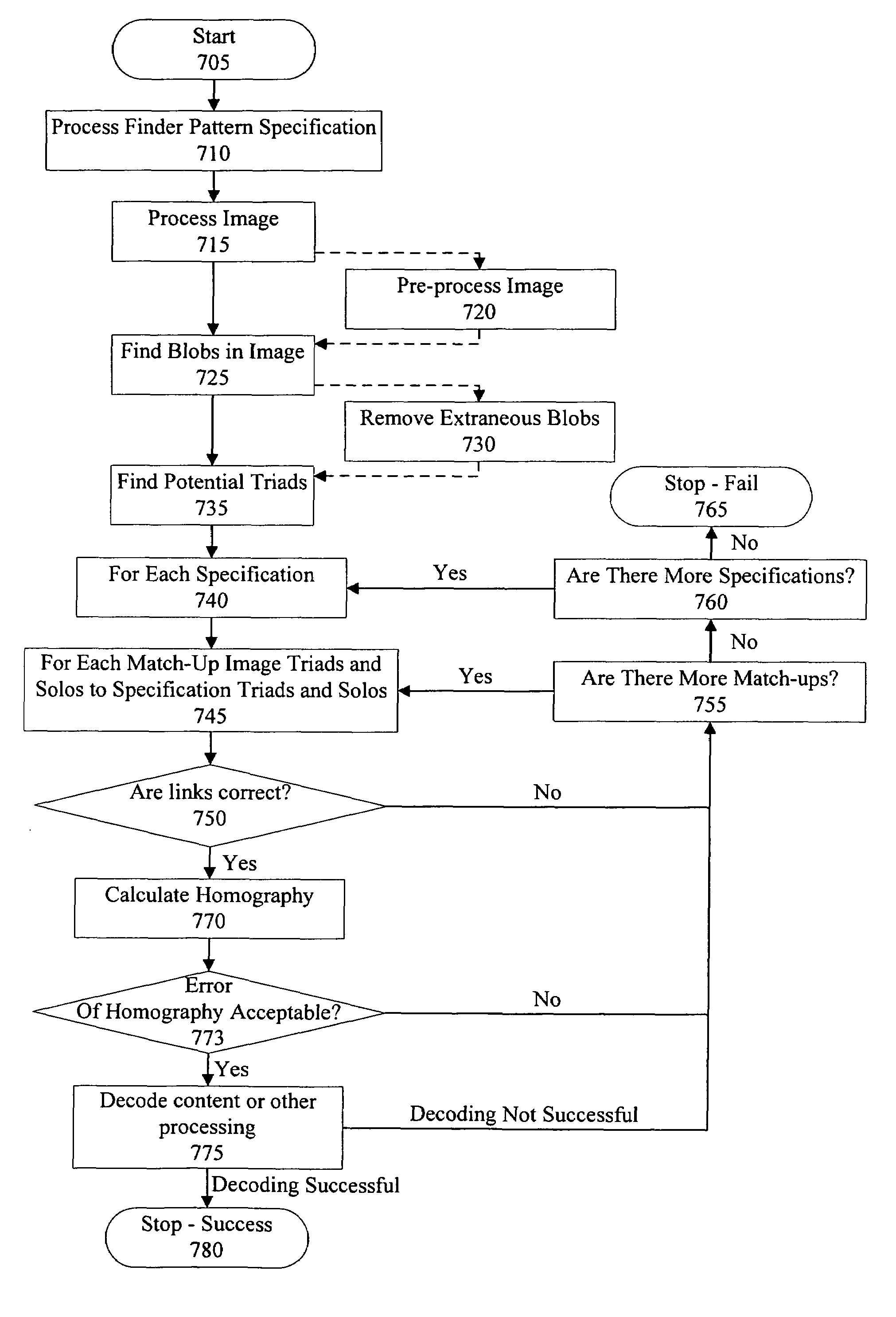
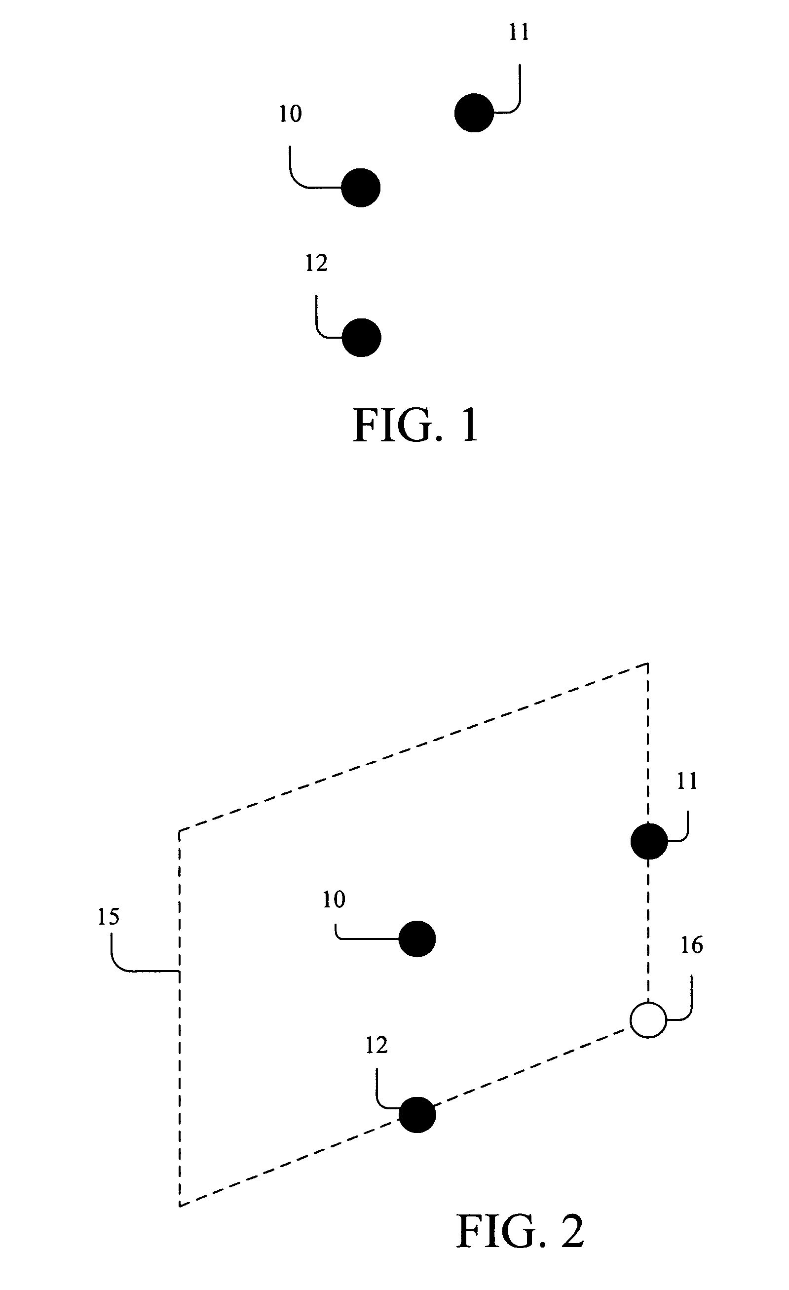
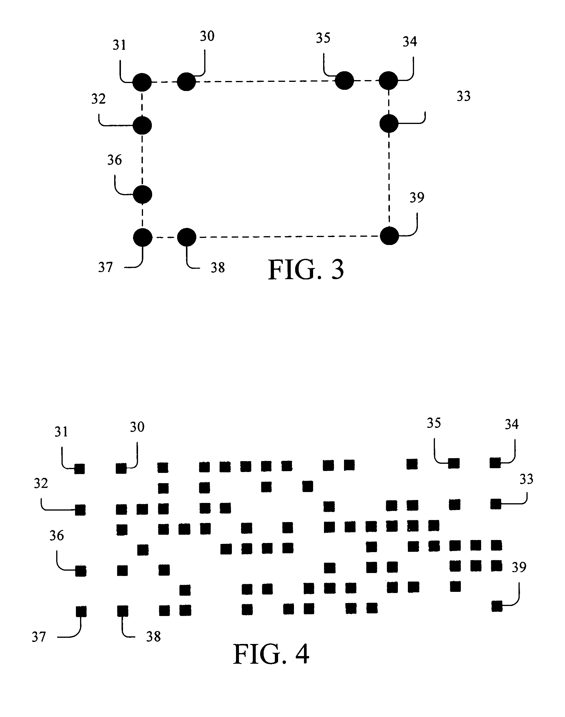
The invention relates to a finder pattern for detection and location of at least one target feature in a target object. The finder pattern includes at least two triads arranged in predetermined locations in the target object, wherein each triad includes a first blob, a second blob, and a third blob, wherein each blob has substantially the same area and is positioned in a predetermined location in the target object. The locations of the first and second blobs are substantially equidistant from the third blob, and the locations of the first, second, and third blobs are not collinear. The invention further relates to a method for detecting a finder pattern in a target object, and a computer readable medium having instructions stored therein for detecting a finder pattern in a target object, which, when executed by a processor of a computing device, cause the computing device to carry out the steps of the method.

Description

RELATED APPLICATION DATA[0001]This application claims the benefit of U.S. Provisional Patent Application No. 60 / 683,350, filed on May 23, 2005, which is hereby incorporated by reference for all purposes as if fully set forth herein.FIELD OF THE INVENTION[0002]The invention relates to the creation and use of finder patterns for efficient detection and coordinate system mapping of target objects. The finder patterns are constructed from a flexible configuration of blob elements having recognizable attributes.BACKGROUND[0003]Conveniently it is known to use finder patterns to find and identify a wide variety of information on articles and products. Finder patterns are present in most machine readable media, such as common barcodes and two dimensional machine readable codes.[0004]Printed one dimensional barcodes like UPC and Code 39 are well known in the art. They read by electronic sensors scanning along a single line through a printed set of parallel lines of varying width which consti...

Claims


Application Information

Patent Timeline
Patent Type & Authority Patents(United States)
IPC IPC(8): G06K9/00
CPCG06K7/1443G06K19/06028G06K19/06131G06K19/06037G06K2009/3225G06V10/245
Inventor SQUIRES, SANFORD R.LEVINGER, JAMES K.
Owner NEXTCODE CORP
Why Eureka
Try Eureka