Commercial lifting device-jack stand frame locking mechanism

a technology of locking mechanism and lifting device, which is applied in the field of commercial systems, can solve the problems of short life, inconvenient redesign, and inability to reliably lock the control frame,

Active Publication Date: 2008-08-19
CALA SALVATORE
View PDF11 Cites 15 Cited by
  • Summary
  • Abstract
  • Description
  • Claims
  • Application Information

AI Technical Summary

Problems solved by technology

It was found that many commercial users would utilize all of their available jack stands, and the power unit was thereafter useless until another jack stand was available to be extracted and reused.
One such design challenge of the jack stand related to a lifting plate raised by the ends of a pair of lift arms on the power unit would sometime shift during lifting, and required redesign of these mating components so they would be self-aligning.
Another design challenge of the jack stand related to a locking mechanism that retained the second frame during elevation of the control frame was not reliable and had a short life, and required redesign with specific new cam angles, materials and heat treating specifications.
Another design challenge of the power unit related to the original hydraulic ram operating on the middle of the lift arms and required excessive and pivotal travel.
Another design challenge was to improve the control features of the handle during use, and to improve the handle for movement of the power unit and for compact storage of the handle on the power unit for shipping and when the power unit was not in use.
Another design challenge was that a manual lift bridge should be provided for the basic power unit, stored at a first position on the power unit; and readily available to be placed at a second position on the forward ends of the lift arms, so that the basic power unit could also function as a load lifting jack.
Another design challenge related to the lift arms of the power unit having an extruded recessed channel in the upper surface for retaining a compression spring for advancing the automatic-slide-forward-bridge.
The lift arms were difficult to manufacture, had a high scrap rate and were thus not robust to produce.
Also, the slide-forward bridge was difficult to produce, was difficult to assemble, and was not as smooth in operation as desired.
Another design challenge resulted from the redesign of the retaining channels for the rearward ends of the lift arms.

Method used


Image

  • Commercial lifting device-jack stand frame locking mechanism
  • Commercial lifting device-jack stand frame locking mechanism
  • Commercial lifting device-jack stand frame locking mechanism

Examples


first embodiment

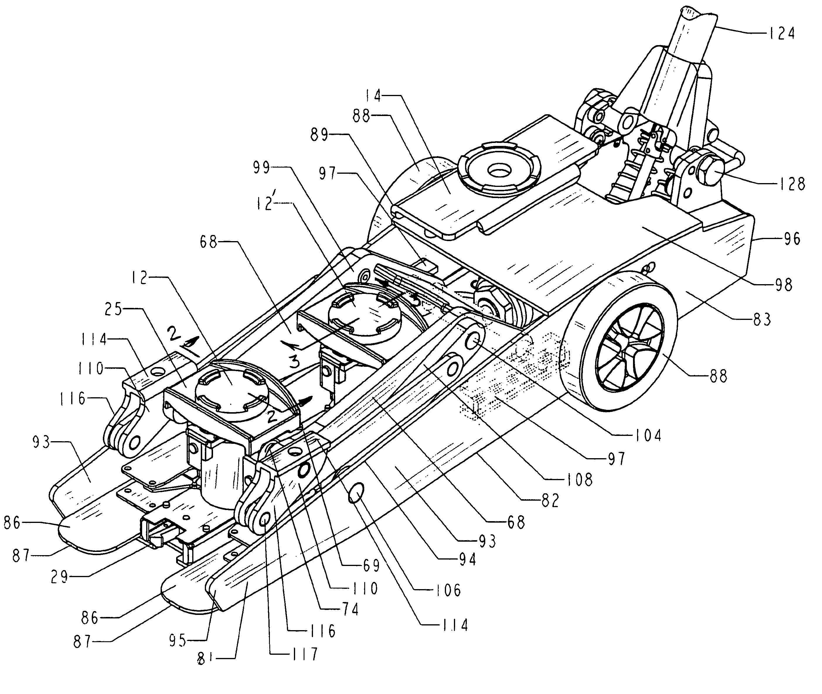
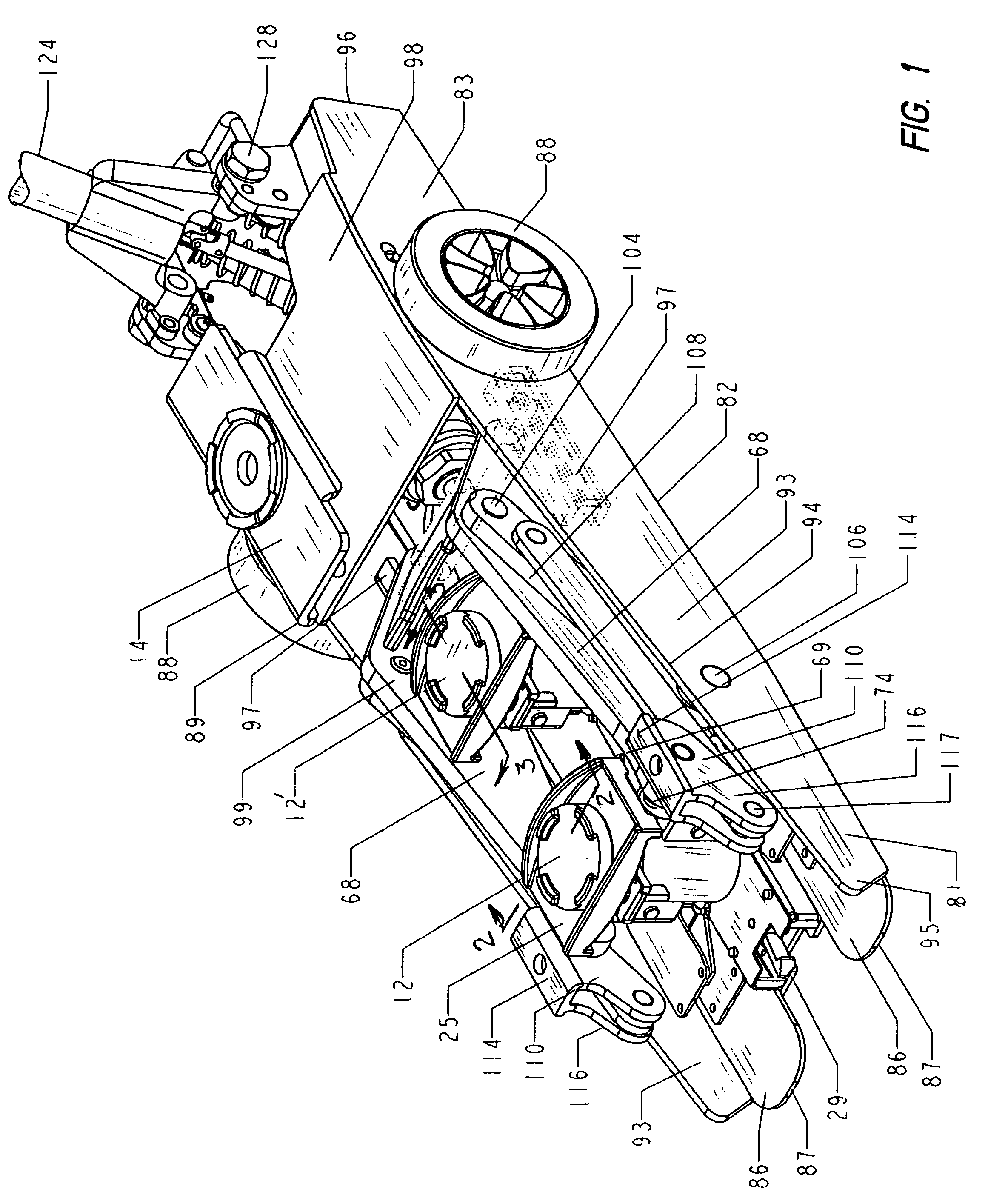
[0072]Referring first to FIG. 1 there is illustrated a mobile power unit 10 of the present invention for conventional use with one or more jack stands 12 and 12′ of the present invention for lifting and supporting a load. The power unit is also readily convertible for use directly as a load lifting jack by a manual two-position lift bridge 14. The lift bridge as shown in FIG. 1 is placed on the power unit in its first (stored) position, and can be manually placed into its second (operative) position (see FIG. 29) on the forward end of the power unit to convert the power unit for use directly as a load-lifting jack. The two-position lift bridge will be discussed later in detail. The jack stands are designed to have a very low initial height, and the power unit is designed to be very sleek, having a smooth, arcuate, low-profile for maneuvering into low lifting applications and having a unique functional and industrial appearance. The system will be discussed in terms of its structure ...

second embodiment

[0162]Referring now to FIGS. 32-34, the two-part lifting system is shown wherein a power unit 230 incorporates an improved automatic-slide-forward-bridge assembly 240. Briefly, the slide forward bridge is slidably retained on the upper surfaces of the lift arms and is always biased toward the forward ends thereof. When the power unit has jack stands loaded in the frame thereof, the jack stands automatically push the bridge rearward along the lift arms, and the power unit is operable for use with the jack stands. When there are no jack stands in the frame of the power unit, and the lift arms are lowered to their lowest position in the frame, the bridge is automatically biased onto the forward ends of the lift arms, and the power unit is operable for use directly as a load lifting jack.

[0163]The power unit 230 features the same components and inter-engagement of the components as previously discussed in reference to power unit 10, except the power unit 230 does not incorporate the two...


PUM


Abstract

An extendible jack stand comprises first, second, and third vertical frames arranged in telescoping relationship. A locking mechanism includes an upwardly extending finger fixedly secured to an outer surface of the upper end of the first frame. A guide member is secured to the upper end of the second frame and extends horizontally outward. A latch member is slideable within the guide member and has a slotted opening therein for receiving the finger, with springs urging the latching member inward. When the third frame is fully extended, the latch member is urged into a groove in the third frame and permits the second frame to be extended. The upper end of the finger has an outward surface that inclined at about 32° for sliding the latch member outward along the guide member. The inward surface then inclines at an angle of about 45°. The inward surface further extends inclined at an angle of about 23. The guide member, the finger and the latch member are formed of 4130-4140 steel and are heat treated to a hardened of about 40-45 Rockwell C.

Description

CROSS REFERENCE TO RELATED APPLICATIONS[0001]Applications have been filed directed to a Commercial Lifting Device-Power Unit, -Self Aligning Jack Stand, -Two-Position Bridge, -Slide-Forward Bridge, -Safety Mechanism, -Handle Controls, -Frame Locking Mechanism, and -Power Unit Controls, as described in the present specification.BACKGROUND OF THE INVENTION[0002]The invention relates to a commercial system for lifting and supporting an object i.e. a corner of an automobile; particularly to a two part jacking system including an improved robust power unit that can be used to place and elevate an improved robust jack stand. The inventor of the present invention is a pioneer of the two part jacking system and holds numerous patents for two part jacking systems, some of which are described below.[0003]Briefly, the commercial two part jacking system consists of a mobile power unit and a set of separate mechanical jack stands. Examples of the two part jacking system and mobile power unit are...

Claims


Application Information

Patent Timeline
Patent Type & Authority Patents(United States)
IPC IPC(8): B66F3/00
CPCB66F5/04B66F1/08B66F13/00
Inventor ARZOUMAN, HARRY H.
Owner CALA SALVATORE
Why Eureka
Try Eureka