Piezoelectric vibrator, filter using the same and its adjusting method
a technology of piezoelectric vibrator and filter, applied in piezoelectric/electrostrictive/magnetostrictive devices, piezoelectric/electrostriction/magnetostriction machines, impedence networks, etc., can solve the problem of not considering the long-term reliability of stress relaxation of each film, and achieve the effect of reducing the gap
- Summary
- Abstract
- Description
- Claims
- Application Information
AI Technical Summary
Benefits of technology
Problems solved by technology
Method used
Image
Examples
first exemplary embodiment
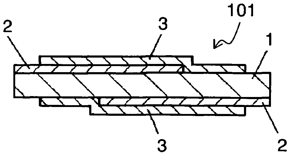
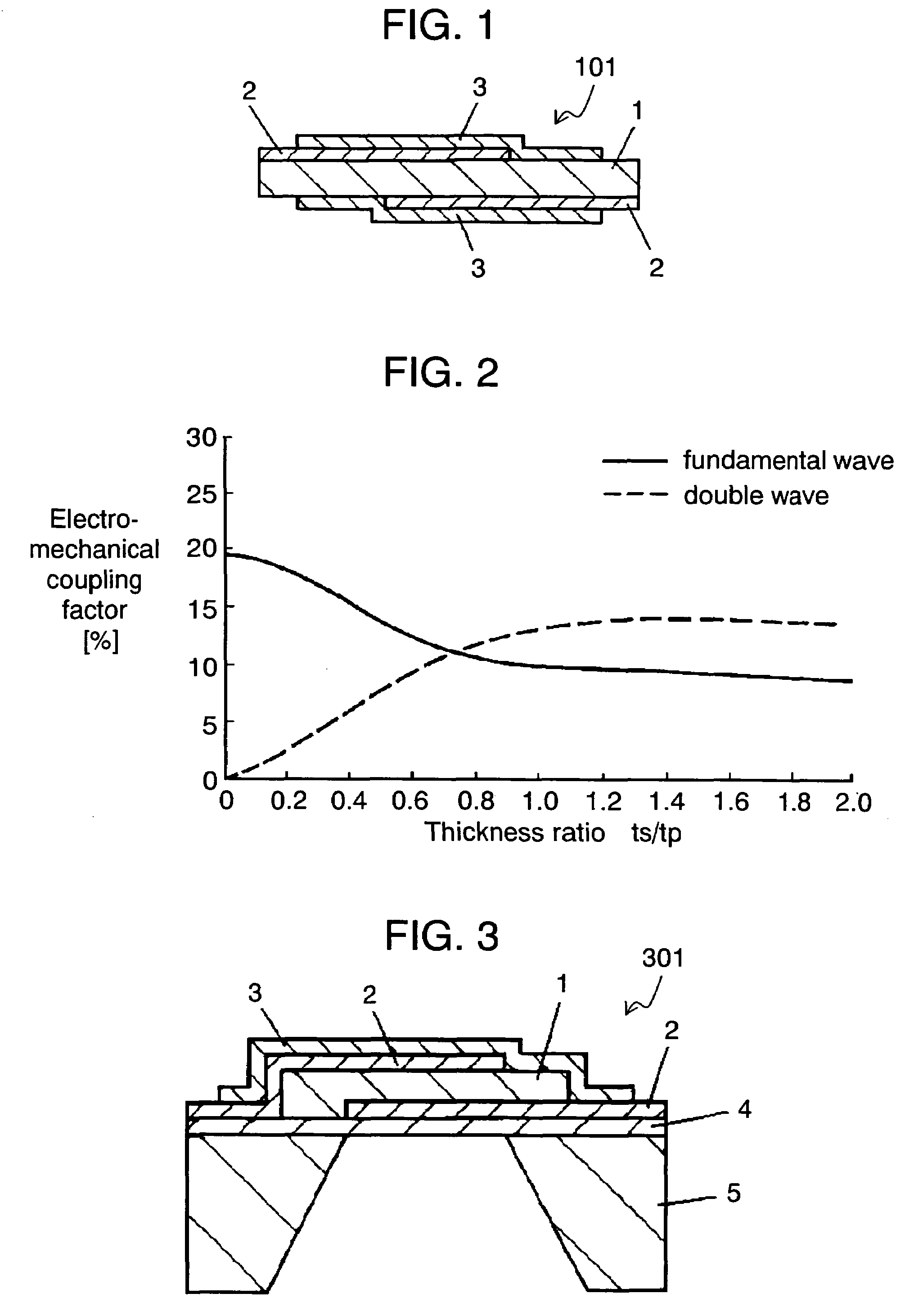
[0020]FIG. 1 is a sectional view showing piezoelectric vibrator 101 which uses aluminum nitride as its piezoelectric material and a fundamental mode of thickness longitudinal vibration as principal vibration. Polarization thereof points in a direction of a thickness of a piezoelectric plate. Piezoelectric vibrator 101 is formed of piezoelectric plate 1 made of aluminum nitride, exciting electrodes 2, facing each other provided at both faces of piezoelectric plate 1 and silicon oxide films 3 disposed on both faces of piezoelectric plate 1 as dielectric films.
[0021]Piezoelectric plate 1 made of aluminum nitride has a thickness of 1 μm. Silicon oxide films 3 are formed at both faces of piezoelectric plate 1 so as to have the same thickness of 0.4 μm and substantially the same area each other. Therefore, a difference of internal stress, which is caused by a difference of stress relaxation in a long term and affects piezoelectric plate 1 or the silicon oxide, becomes small. Accordingly, ...
second exemplary embodiment
[0032]FIG. 3 is a sectional view showing piezoelectric vibrator 301 which uses aluminum nitride as its piezoelectric material and a 2nd overtone mode of thickness longitudinal vibration as principal vibration. Polarization thereof points in a direction of a thickness of a piezoelectric plate. Piezoelectric vibrator 301 is formed of piezoelectric plate 1 made of aluminum nitride, exciting electrodes 2, facing each other, provided at both faces of piezoelectric plate 1, silicon oxide film 3, which is used as a first dielectric film, disposed on a back face of piezoelectric plate 1 and silicon nitride film 4, which is used as a second dielectric film, disposed on a front face of piezoelectric plate 1. Supporting substrate 5 supports piezoelectric vibrator 301.
[0033]Piezoelectric plate 1 made of aluminum nitride has a thickness of 10 μm. Silicon oxide film 3 has a thickness of 4 μm, and silicon nitride film 4 has a thickness of 5 μm, so that dielectric films having substantially the sam...
third exemplary embodiment
[0042]A band-pass filter, which can pass signals in specific frequencies, is known to be produced by combining a plurality of piezoelectric vibrators. In general, a ladder type filter, which uses a resonance frequency or an anti-resonance frequency of a vibrator as a pole of a filter characteristic and uses an interval between the resonance frequency and the anti-resonance frequency as a pass band, is provided. FIG. 4 shows an electrical equivalent circuit of the ladder type filter using two piezoelectric vibrators 501.
[0043]FIG. 5 shows ladder type filter 502 which is formed by a connection shown in the electrical equivalent circuit of FIG. 4. Ladder type filter 502 uses two piezoelectric vibrators 501 which uses aluminum nitride as its piezoelectric material and a fundamental mode of thickness longitudinal vibration as principal vibration. Polarization thereof points in a direction of a thickness of a piezoelectric plate. Ladder type filter 502 is formed of piezoelectric vibrators...
PUM
 Abstract
Description
Claims
Application Information
 - R&D
- Intellectual Property
- Life Sciences
- Materials
- Tech Scout
- Unparalleled Data Quality
- Higher Quality Content
- 60% Fewer Hallucinations
Browse by: Latest US Patents, China's latest patents, Technical Efficacy Thesaurus, Application Domain, Technology Topic, Popular Technical Reports.
© 2025 PatSnap. All rights reserved.Legal|Privacy policy|Modern Slavery Act Transparency Statement|Sitemap|About US| Contact US: help@patsnap.com


