
MIMO transmission and reception methods and devices

a technology of receiving method and transmission method, applied in the direction of orthogonal multiplex, multiple modulation transmitter/receiver arrangement, baseband system details, etc., can solve the problem of large quantization error of analog to digital converter, adversely affecting processing after the conversion, and greatly deteriorating receiving performan

Inactive Publication Date: 2008-08-19
KK TOSHIBA
View PDF11 Cites 59 Cited by
  • Summary
  • Abstract
  • Description
  • Claims
  • Application Information

AI Technical Summary

Problems solved by technology

Unfortunately, other transmit antennas than the transmit antenna which transmits the short preamble sequence transmit nothing before the long preamble sequence.
If the received level is lower than the lower limit of the input dynamic range, the analog to digital converter produces a large quantization error.
In either case, the analog to digital converter cannot appropriately convert a signal, and this adversely affects processing after the conversion.
Accordingly, the problems of the saturation and quantization error of the analog to digital converter described above become significant, and the receiving performance greatly deteriorates.
On the transmission side as described above, a plurality of transmitters corresponding to a plurality of transmit antennas cannot be given equal structures, and this complicates the whole transmitter apparatus.
In addition, since the power consumption of the transmitter apparatus strongly depends on the transmission output level, this is not advantageous in achieving low power consumption.

Method used


Image

  • MIMO transmission and reception methods and devices
  • MIMO transmission and reception methods and devices
  • MIMO transmission and reception methods and devices

Examples


Embodiment Construction

[0033]Embodiments of the present invention will be described in detail below with reference to the accompanying drawing.

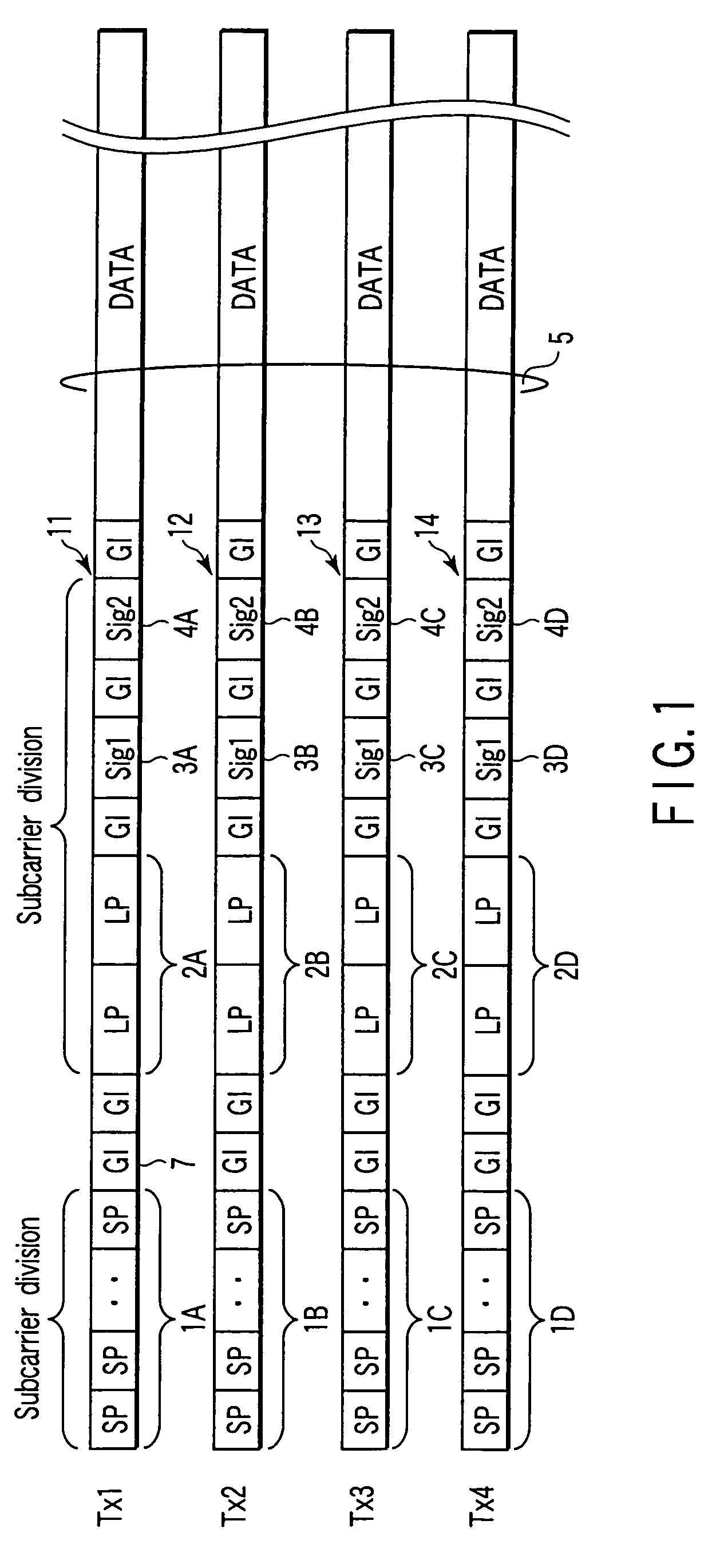
[0034]A preamble according to an embodiment of the present invention contains first to fourth physical layer convergence protocol (PLCP) signals 11 to 14 transmitted from transmit antennas Tx1 to Tx4. The PLCP signals 11 to 14 includes short preamble sequences 1A to 1D, long preamble sequences 2A to 2D, first signal fields (Sig1) 3A to 3D, and second signal fields (Sig2) 4A to 4D. The transmit antenna Tx1 transmits the short preamble sequence 1A, long preamble sequence 2A, first signal field 3A, and second signal field 4A of the first PLCP signal 11 in order. Likewise, the antenna Tx2 transmits 1B, 2B, 3B, and 4B of the second PLCP signal 12 in order, the antenna Tx3 transmits 1C, 2C, 3C, and 4C of the third PLCP signal 13 in order, and the antenna Tx4 transmits 1D, 2D, 3D, and 4D of the fourth PLCP signal 14 in order.

[0035]Unit preambles SP contained in the short ...


PUM


Abstract

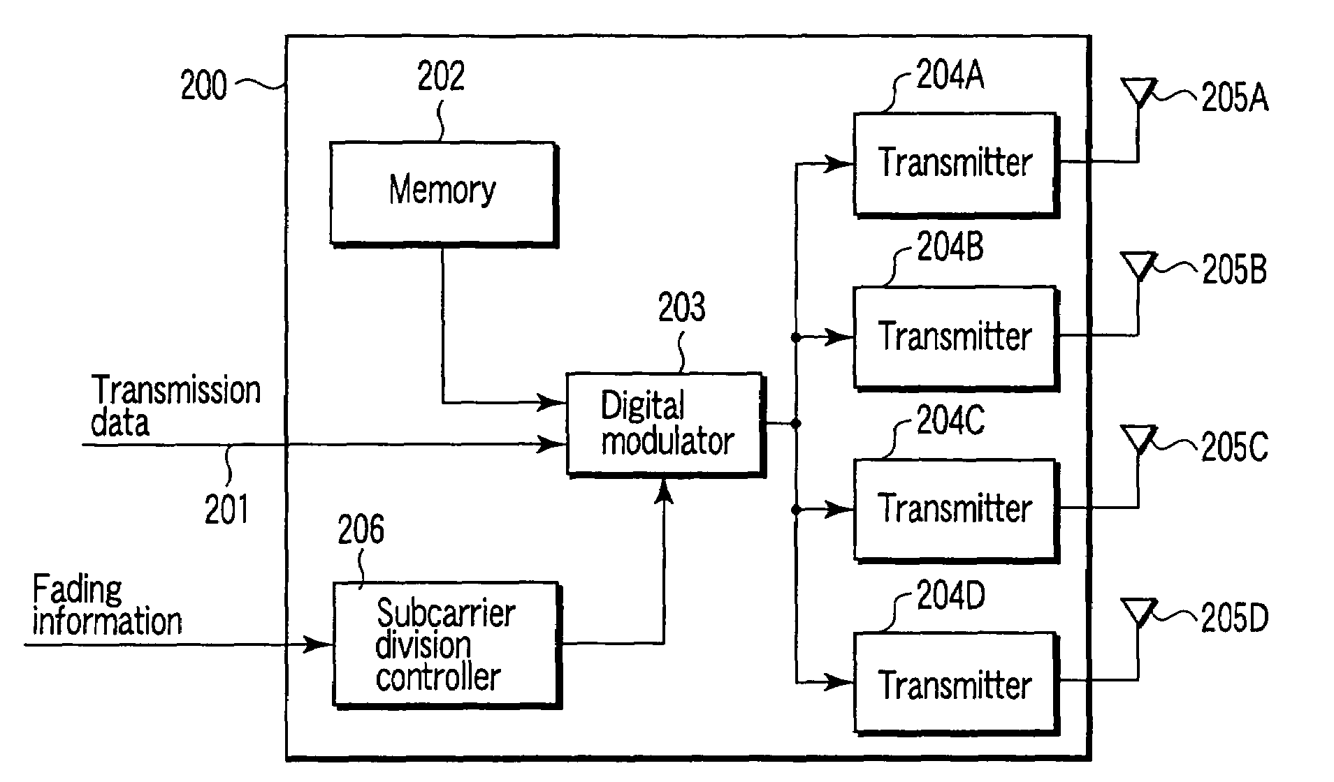
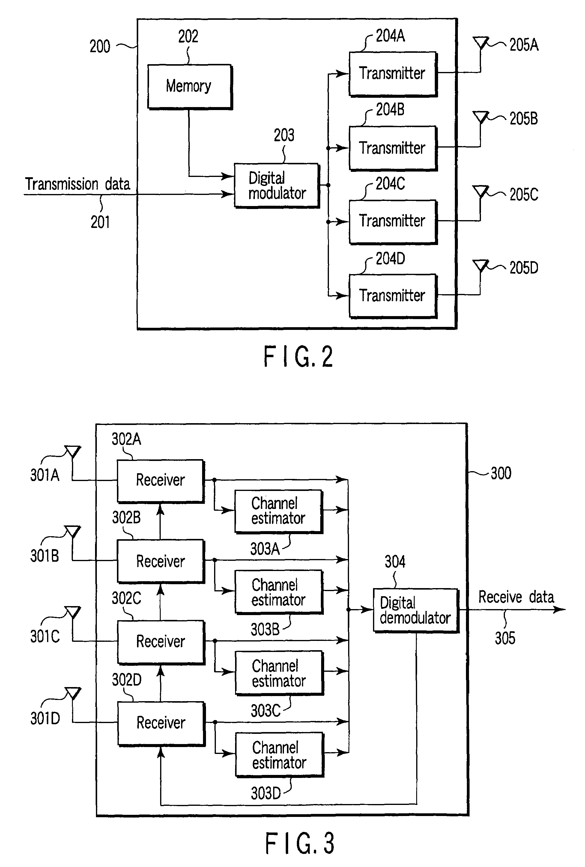
In a wireless transmitting device which performs transmission by an OFDM using a plurality of subcarriers orthogonal to each other, a plurality of preambles to which a plurality of different subcarrier groups selected from a plurality of subcarriers within an OFDM signal band are allocated are transmitted by using a plurality of transmit antennas, and data is transmitted by using the antennas after the preambles are transmitted.

Description

CROSS-REFERENCE TO RELATED APPLICATIONS[0001]This application is based upon and claims the benefit of priority from prior Japanese Patent Application No. 2004-004848, filed Jan. 9, 2004, the entire contents of which are incorporated herein by reference.BACKGROUND OF THE INVENTION[0002]1. Field of the Invention[0003]The present invention relates particularly to a wireless transmitting device, wireless receiving device, wireless transmitting method and wireless receiving method by which preamble are transmitted before data.[0004]2. Description of the Related Art[0005]The institute of Electrical and Electronics Engineers (IEEE) is establishing a wireless LAN standard called IEEE 802.11n which aims at a throughput of 100 Mbps or more. In IEEE 802.11n, a technique called multi-input multi-output (MIMO) which uses a plurality of antennas at transmitters and receivers, may be adopted. IEEE 802.11n is required to coexist with the existing IEEE 802.11a. In the MIMO technique, to measure resp...

Claims


Application Information

Patent Timeline
Patent Type & Authority Patents(United States)
IPC IPC(8): H04K1/10H04B7/02H04L1/02H04L27/28H04J11/00H04B7/04H04B7/06H04J99/00H04L27/26
CPCH04L1/06H04L5/0023H04L5/0048H04L27/0008H04L25/0204H04L25/0226H04L5/0064
Inventor SETO, ICHIROAOKI, TSUGUHIDEYOSHIDA, HIROSHI
Owner KK TOSHIBA
Learn More