Electronic field device with a sensor unit for capacitive level measurement in a container

a sensor unit and electronic field technology, applied in the direction of liquid/fluent solid measurement, volume measurement, volume measurement, etc., can solve the problems of parasitic inductance, long probes, inaccuracy of measurement, etc., and achieve the effect of easy adaptation

Inactive Publication Date: 2008-08-19
EHNDRESS KHAUZER GMBKH KO KG
View PDF12 Cites 15 Cited by
  • Summary
  • Abstract
  • Description
  • Claims
  • Application Information

AI Technical Summary

Benefits of technology

[0006]An object of the invention is to provide a field device electronics having a sensor unit for capacitive fill level measurements in a container, being easy to adapt for given field conditions, and using the best-suited measuring method as a function of the given, concrete application.
[0008]A main idea of the invention is to apply a microprocessor for a production of voltage signals, for an evaluation of the measurement current, for a compensation of interference parameters, and for an ascertaining of the parameters of the sensor-container arrangement which are to be determined, with the associated programs being stored in a memory unit. For evaluation by the microprocessor, the analog measurement current is digitized by means of an analog / digital converter. Use of a microprocessor makes it possible, in simple manner, to select and apply optimum measuring methods for the existing field conditions. Only the program needed for the measuring method is brought from the memory unit and executed.
[0013]By dividing the processor clock signal, the voltage signal can be given practically any measuring frequency beneath that of the processor clock. Thus, the frequency switch can be realized, without problem, by programming. This has, on the one hard, the advantage that the electronics can be adapted for different applications and that, moreover, a simple compensation of the parallel conductivity can be achieved by alternatingly measuring with two different measuring frequencies.
[0028]In an especially advantageous embodiment of the invention, measurements are not made continuously, but, instead, separate sinusoidal bursts containing, for example, 1000 oscillations are produced and evaluated during a measurement cycle. Between the separate sinusoidal bursts lie pauses, with the lengths of the pauses being variable and determined, for example, by a random generator. In this manner, an increased insensitivity to stray electromagnetic interferences is achieved, since no continuous interactions between measurement signal and interfering signal can arise.

Problems solved by technology

The apparent current is, however, not only dependent on capacitance, but also on the conductivity of the medium to be measured, a fact which leads, in practice, to inaccuracies in the measurement, since the conductivity depends, especially in the case of bulk goods, on different factors, such as e.g. temperature and humidity.
However, experience shows that measurement at high frequencies (>100 kHz) leads to difficulties with long probes in the form of large, parasitic inductances.
With this method, however, there is the disadvantage that e.g. in media with small dielectric constant and large conductivity, in which measurements using apparent current measurement are possible without problem, difficulties arise because reactive current practically disappears.
Moreover, such conventional synchronous rectifier circuits have proven to be sensitive with respect to electromagnetic interferences.

Method used


Image

  • Electronic field device with a sensor unit for capacitive level measurement in a container
  • Electronic field device with a sensor unit for capacitive level measurement in a container
  • Electronic field device with a sensor unit for capacitive level measurement in a container

Examples


Embodiment Construction

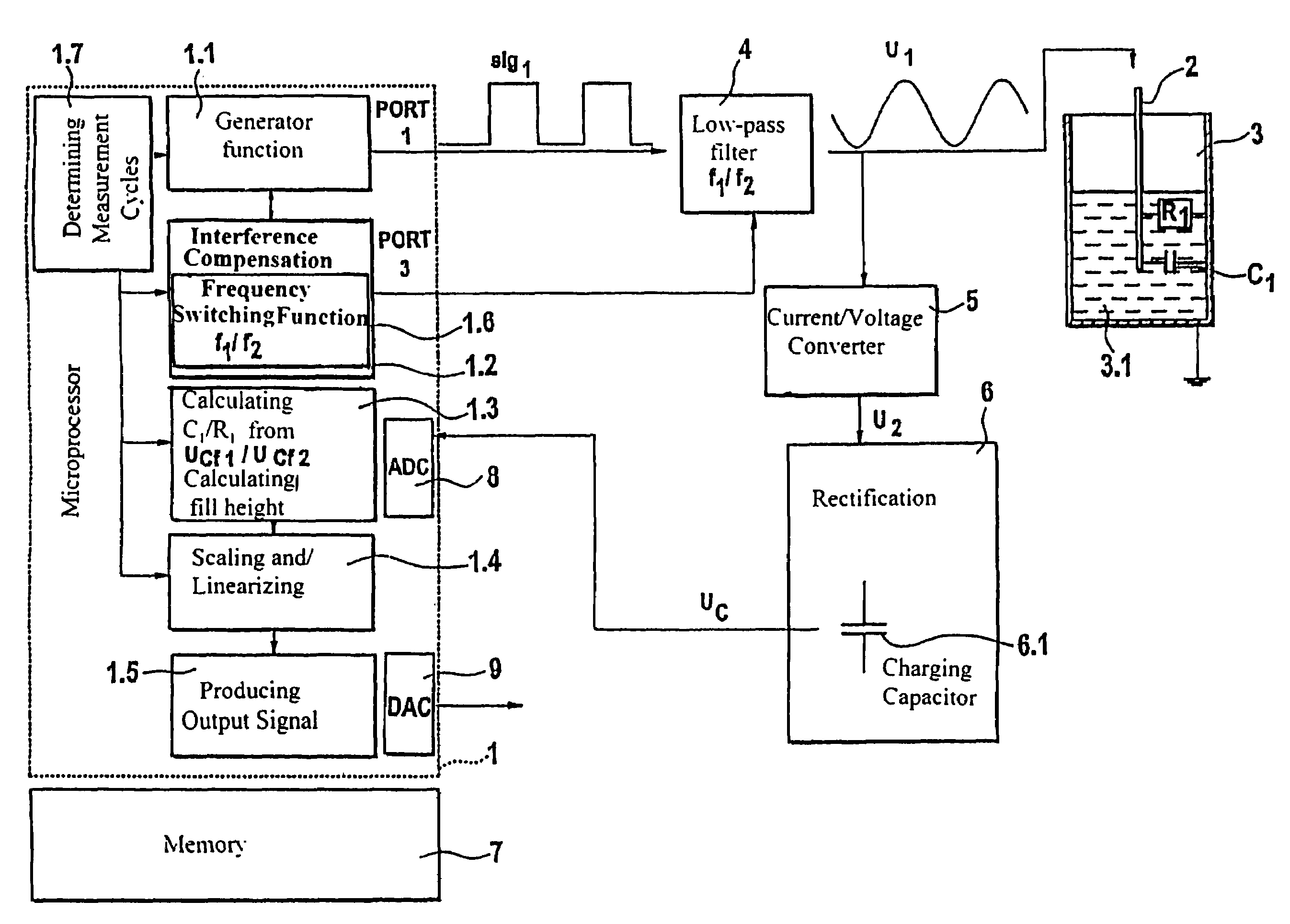
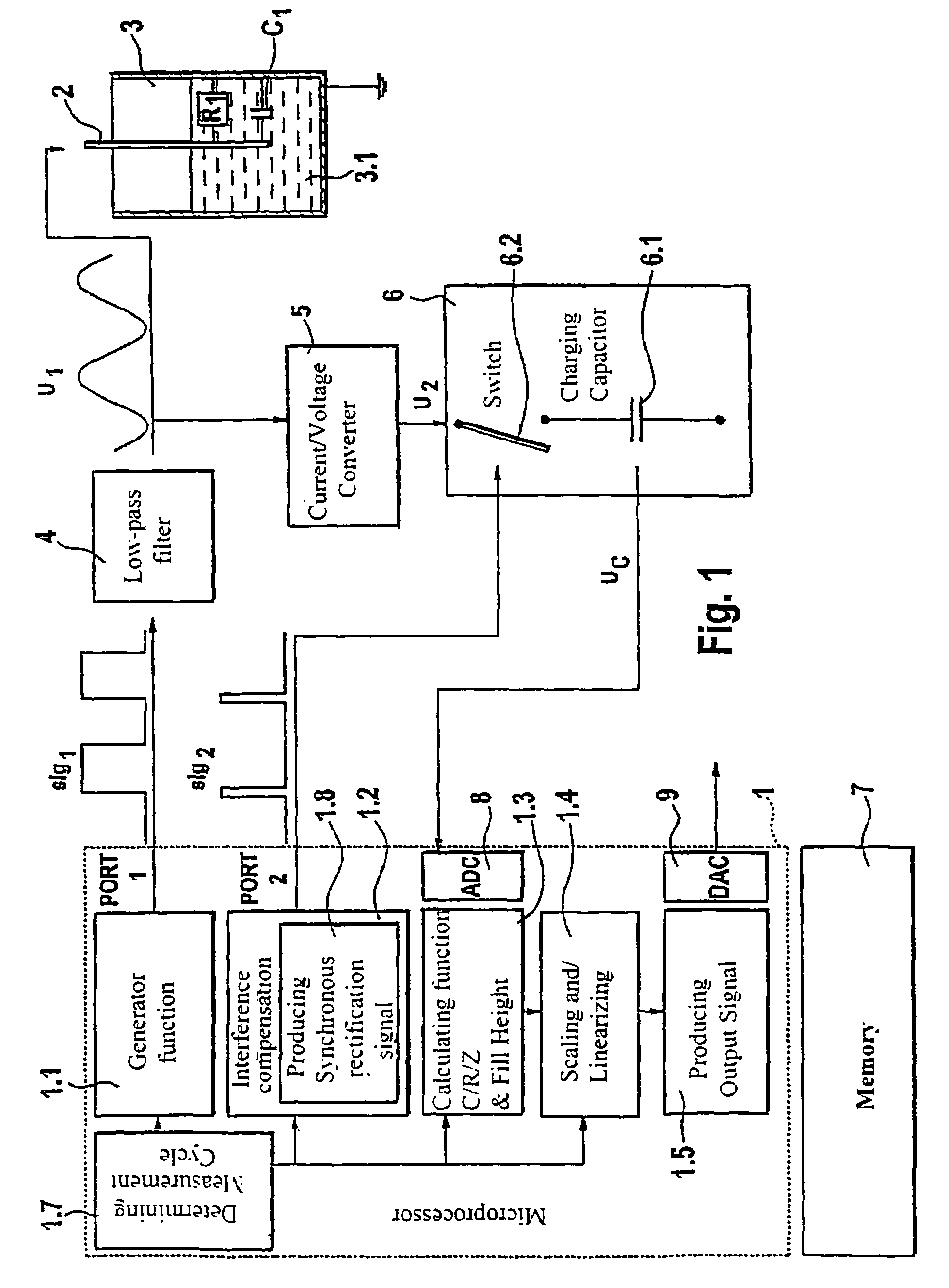
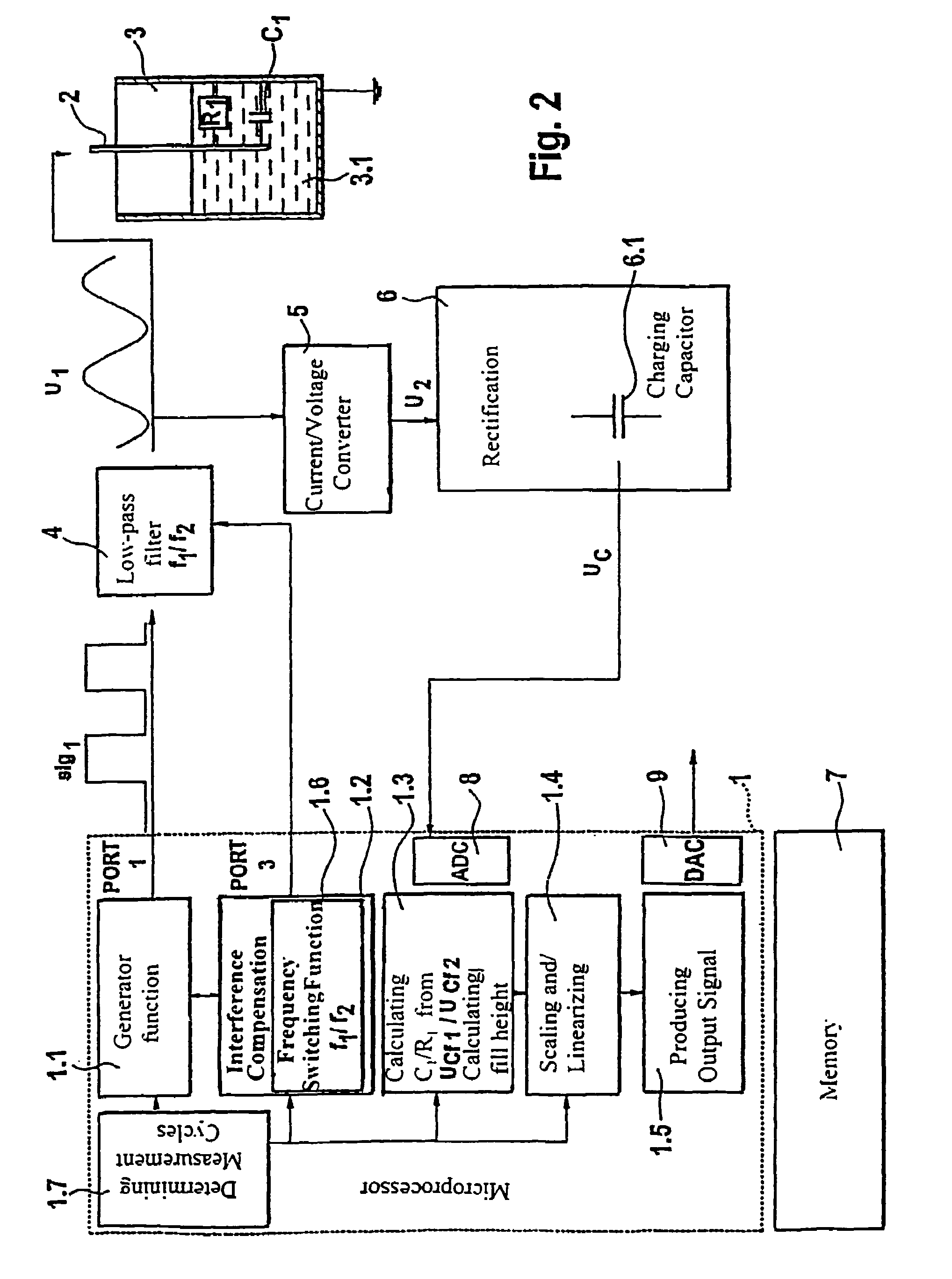
[0035]As can be seen from FIGS. 1 and 2, the field device electronics includes a microprocessor 1, a sensor 2 for determining the fill level of a medium 3.1 in a container 3, a filter 4, a current / voltage converter 5, a memory unit 7 and a rectifier 6, with the rectifier 6 including a charging capacitor 6.1.

[0036]As can be seen from FIG. 1, the microprocessor 1 includes, for performing a first measuring method, the function blocks: Generator function 1.1, interference-parameter compensation 1.2, calculating function 1.3, scaling / linerarizing 1.4, producing output signal 1.5. Additionally, there is a function block 1.7 present, “Establishing Measurement Cycle”, which determines the length of the measurement cycle and the pause duration between the measurement cycles. This enables the lowering of current consumption by means of an energy saving mode. Additionally, by varying the pause durations, an increased insensitivity to stray electromagnetic interferences is achieved, since no co...


PUM


Abstract

A field device electronics with a sensor unit for capacitive fill level measurements in a container, wherein the field device electronics is connected over appropriate signal paths with the sensor unit, wherein the field device electronics produces a voltage signal for driving the sensor unit and receives and evaluates a measurement current from the sensor unit. According to the invention, an analog / digital converter digitizing the analog measurement current, a microprocessor and a memory unit are present, wherein the microprocessor utilizes predetermined program routines to perform the production of the voltage signal and the evaluation of the measurement current and a compensation of interference parameters and a determination of the parameters of the sensor-container arrangement which are to be determined, with the associated programs being stored in the memory unit.

Description

FIELD OF THE INVENTION[0001]The invention relates to a field device electronics with a sensor unit for capacitive fill level measurements in a container wherein the field device electronics is connected over appropriate signal paths with the sensor unit, produces a voltage signal (sig1) for driving the sensor unit, and receives and evaluates a measurement current from the sensor unit.BACKGROUND OF THE INVENTION[0002]Field devices for capacitive fill level measurement have been known for many years. In these devices, a probe extending into the container forms a capacitor with the container wall. The capacitance of the capacitor created in this way depends on the fill level and the dielectric constant of the medium to be measured.[0003]A possibility for measuring this capacitance is the so-called apparent current measurement method. In this, a conventional rectifying circuit is used to measure the amount of the alternating current flowing through the capacitor formed from probe, mediu...

Claims


Application Information

Patent Timeline
Patent Type & Authority Patents(United States)
IPC IPC(8): G01F23/00G06F17/00G01D1/00G01D3/02G01F23/26
CPCG01D3/02G01F23/266G01F23/263
Inventor FLORENZ, HANS-JORGHEILEG, CLEMENS
Owner EHNDRESS KHAUZER GMBKH KO KG
Why Eureka
Try Eureka