Bubble generator for use in doppler ultrasonic flowmeter and doppler ultrasonic flowmeter

a technology of ultrasonic flowmeter and bubble generator, which is applied in ultrasonic/sonic/infrasonic diagnostics, instruments, liquid/fluent solid measurements, etc., can solve the problems of insufficient refractive echo intensity, inability to measure, and inability to obtain accurate flow velocity distribution

Inactive Publication Date: 2008-08-26
TOKYO ELECTRIC POWER CO HLDG INC +1
View PDF9 Cites 9 Cited by
  • Summary
  • Abstract
  • Description
  • Claims
  • Application Information

AI Technical Summary

Benefits of technology

[0025]Therefore, the “Venturi tube” having a shape capable of narrowing around the center of its flow path in the longitudinal direction is adopted as a member of the bubble generation member. The difference in pressures caused due to the narrowed flow path serves to let the bubbles in the liquid have the uniform size. Further, it is designed to be returned into the fluid pipe together with the bubbles fed into the fluid pipe via the Venturi tube. Therefore, the liquid and gas are mixed in the Venturi tube, and the bubble generation member feeds the bubbles into the fluid to be measured as the liquid mixed with the bubbles, and at the same time, the liquid to feed is designed be the fluid to be measured drawn out by the negative pressure generating device, so that the effect on the fluid to be measured in view of the flow velocity change is designed to be minimum.
[0029]Accordingly, the bubble generation member and the uniform dispersion member are designed to be disposed at a section being perpendicular to the longitudinal direction of the fluid pipe, so that the bubble generator can be set at a single joint portion of the fluid pipe. Further, the center line along the axial direction of the Venturi tube is designed to be perpendicular to the center line along the axial direction of the fluid pipe, so that a setting work of the Venturi tube can be performed easily and accurately.
[0032]When the fluid pipe in which the fluid to be measured flows has a large pipe diameter, it is difficult to disperse the bubbles uniformly in the pipe by a single bubble generation member. Accordingly, the bubble generation member and the uniform dispersion member are provided two or more, respectively, in number, and the respective pairs are formed to position symmetrically to each other around the pipe. With this, even when the fluid pipe has a large pipe diameter, the bubbles are easily dispersed uniformly in the pipe.
[0036]Since the bubble generator has the plural types of Venturi tubes, it is possible to generate the bubbles which are appropriate for the flow rate measurement by selecting or pairing the appropriate Venturi tube in accordance with the conditions such as the type of the fluid to be measured, the flow velocity, the pipe diameter, and so on.
[0057]As to the Venturi tube, the Venturi tube may be provided with the bubble growing region formed based on a variable length structure that allows the axial length of the Venturi tube to vary. Further, as described in another embodiment the Venturi tube may be formed by having the optimal length computing means or the optimal length control section controlling the axial length of the Venturi tube of the variable length structure.

Problems solved by technology

When the fluid has no reflective body therein, the measurement is impossible.
Still, when the refractive bodies are not mixed into the fluid uniformly, the flow velocity distribution lacks, so that the accurate flow velocity distribution can not be obtained.
However, the injection of the gas was performed using a nozzle inserted into the fluid pipe, a sufficient refractive echo intensity could not be obtained unless the gas grows to a size appropriate for the reflection of the ultrasonic waves used for the measurement in the fluid to be measured.
Besides, it is impossible to obtain the appropriate flow velocity distribution unless the gas is dispersed uniformly in the emitting direction of the ultrasonic pulses.

Method used


Image

  • Bubble generator for use in doppler ultrasonic flowmeter and doppler ultrasonic flowmeter
  • Bubble generator for use in doppler ultrasonic flowmeter and doppler ultrasonic flowmeter
  • Bubble generator for use in doppler ultrasonic flowmeter and doppler ultrasonic flowmeter

Examples


Embodiment Construction

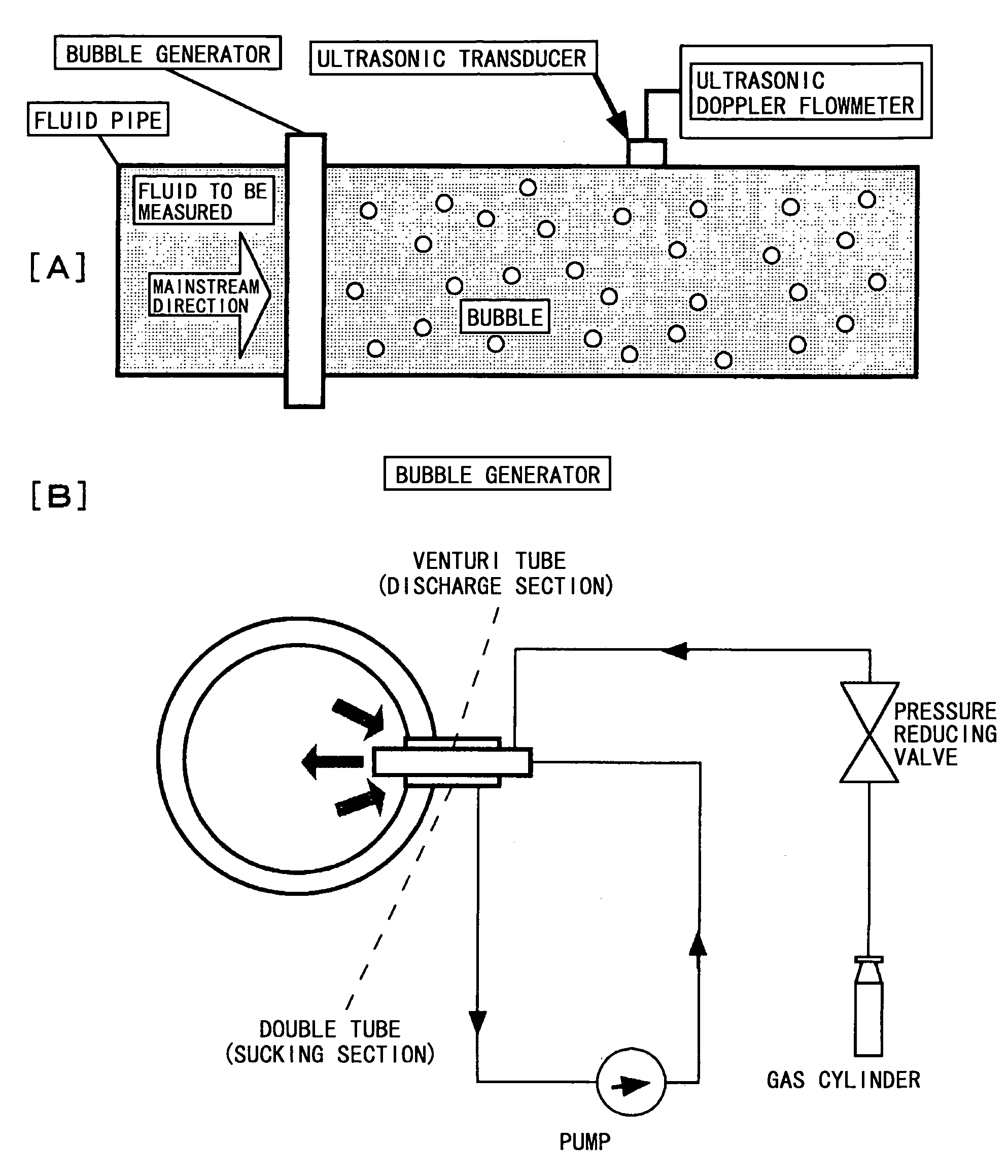
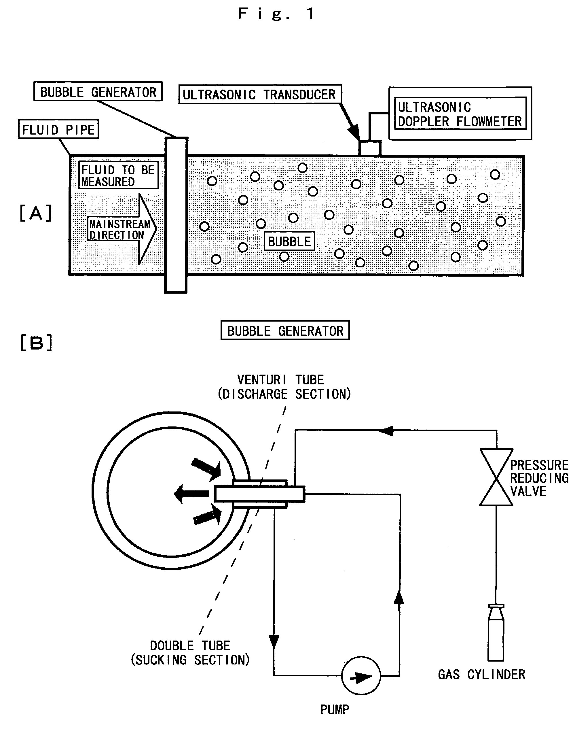
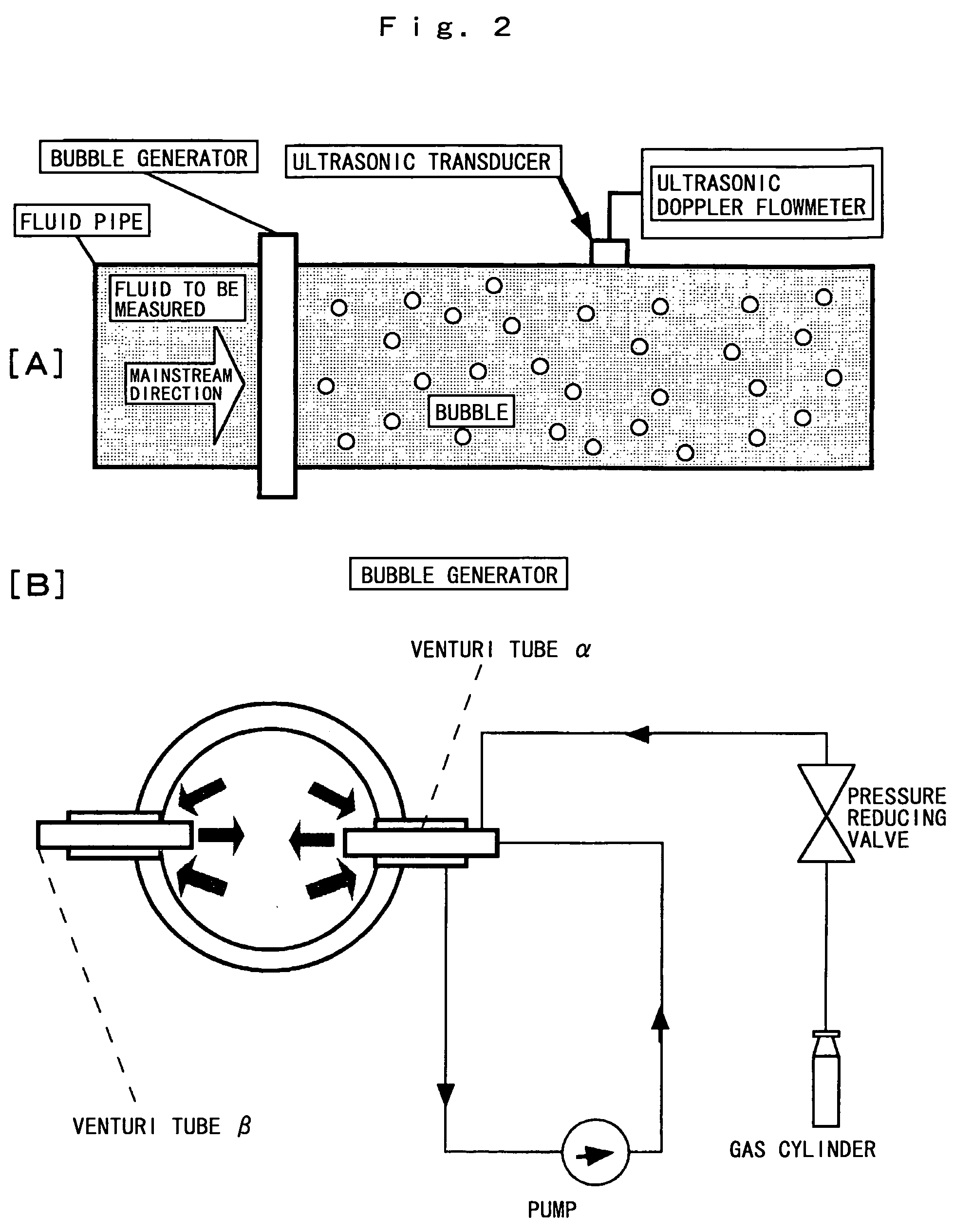
[0070]Embodiments of a bubble generator and a Doppler ultrasonic flowmeter according to the present invention will be described with reference to the attached drawings. The drawings utilized here are FIG. 1 to FIG. 9. FIG. 1 to FIG. 3 are schematic diagrams showing a structure of the embodiment according to the present invention. FIG. 4 is a table showing a measurement result related to a flow rate of a Venturi tube, a flow rate of a gas and a flow rate of the fluid to be measured. FIG. 5 is a view showing an output screen as to a flow velocity distribution of the fluid to be measured. FIG. 6 is a sectional view of a specific Venturi tube. FIG. 7 is a schematic diagram showing a function of the Venturi tube. FIG. 8 is a sectional view in the case of the Venturi tube provided with an additional function. FIG. 9 is a schematic diagram showing a control mechanism to the additional function of the Venturi tube.

[0071](FIG. 1)

[0072]In FIG. 1(A), the case where industrial water flows as a ...


PUM


Abstract

A bubble generator to bring out performance of a Doppler ultrasonic flowmeter to the maximum extent is provided.The bubble generator is provided with a bubble generation member generating bubbles suitable for a predetermined frequency of an ultrasonic pulse emitted into a fluid to be measured and feeding the bubbles into the fluid pipe, and a uniform dispersion member dispersing the bubbles fed uniformly in the pipe, the bubble generator is installed on an upstream side of the fluid pipe with respect to an ultrasonic transducer. The bubble generation member has a Venturi tube, and the uniform dispersion member has a negative pressure generating device, in which the fluid to be measured drawn out by the uniform dispersion member from inside the fluid pipe is returned into the fluid pipe together with the bubbles fed into the fluid pipe via the Venturi tube.

Description

TECHNICAL FIELD[0001]The present invention relates to a Doppler ultrasonic flowmeter capable of measuring a flow rate of a fluid to be measured based on a flow velocity distribution in a measurement region instantly on a time-dependant basis, and an art related thereto.BACKGROUND ART[0002]In Japanese Patent Application Laid-Open No. 2000-97742, there is disclosed a Doppler ultrasonic flowmeter that permits precise, highly accurate and contactless measurement on a time-dependant basis even in the case of a flow in an unsteady state.[0003]Patent document 1: Japanese Patent Application Laid-Open No. 2000-97742.[0004]The Doppler ultrasonic flowmeter disclosed here has a structure as described below. Specifically, it has an ultrasonic transmitting means emitting an ultrasonic pulse of a predetermined frequency from an ultrasonic transducer into the fluid to be measured along a measurement line, a fluid velocity distribution measuring means receiving, out of the ultrasonic pulses emitted ...

Claims


Application Information

Patent Timeline
Patent Type & Authority Patents(United States)
IPC IPC(8): G01F1/20G01F1/66G01F1/704
CPCG01F1/663
Inventor TAKEDAMORI, MICHITSUGUTEZUKA, KENICHITEZUKA, HIDEAKI
Owner TOKYO ELECTRIC POWER CO HLDG INC
Why Eureka
Try Eureka