Brake system with integrated car load compensating arrangement

a technology of load compensating arrangement and brake system, which is applied in the direction of brake system, fluid actuated drum brake, hoisting equipment, etc., can solve the problems of undesirable situation and the large load imposed by the cars on their respective wheel trucks, and achieve the effect of high braking efficiency

Active Publication Date: 2008-08-26
WABTEC HLDG CORP
View PDF14 Cites 54 Cited by
  • Summary
  • Abstract
  • Description
  • Claims
  • Application Information

AI Technical Summary

Benefits of technology

[0010]Still another object of the present invention is to provide a simple, light weight truck mounted brake system for wheel trucks which uses standard truck components and brake beams, provides high braking efficiency, and includes automatic slack adjustment for brake shoe wear in addition to compensating for car loading.

Problems solved by technology

As is well known in the railway industry, one of the major problems arising in all railway car brake systems is that the load imposed by the cars on their respective wheel trucks can vary considerably from car to car and truck to truck.
Obviously, as would be expected, this situation is undesirable.

Method used


Image

  • Brake system with integrated car load compensating arrangement
  • Brake system with integrated car load compensating arrangement
  • Brake system with integrated car load compensating arrangement

Examples


first embodiment

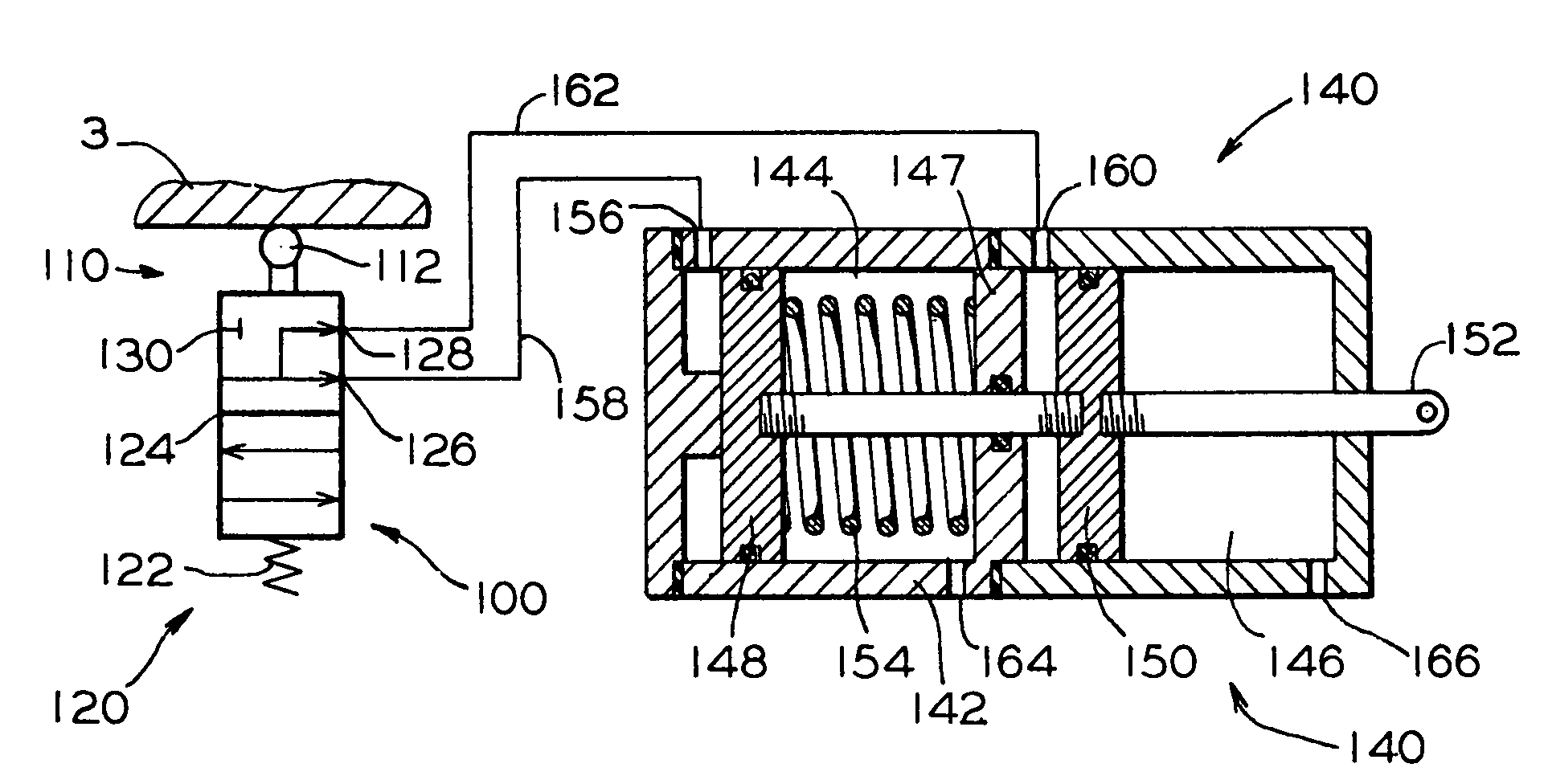
[0024]In the present invention, best shown in FIG. 3, there is means, generally designated 100, for sensing a load on the railway car 2 and generating at least one control signal responsive to such load. Preferably, such means 100 is a valve means which includes a linearly movable means 110 cooperating with a predetermined portion 3, vertically movable, of the railway car 2 or the movable bolster member 16 to sense a vertical position thereof and means, generally designated 120, attached directly to the side frame 12 or to an intermediate member (not shown) attached to such side frame 12 and engageable with or connectable to such sensor means 110 to generate at least one control signal responsive to the position of such predetermined portion 3 or the bolster member 16.

[0025]It will be appreciated that the mounting of the sensor means 110 and signal generating means 120 may be reversed without affecting operation of the present invention.

[0026]Preferably, the sensor means 110 is prov...

second embodiment

[0032]In the present invention, best shown in FIG. 4, either the brake system 20 of FIG. 1 or the brake system 50 of FIG. 2 is provided with an actuator, generally designated 180, comprising a first air spring actuator 182 having an inlet port 184 connectable to first outlet port 126 of the flow control valve 120 via the first control line 158. Such first air spring actuator 182 is disposed within a second air spring actuator 188 which has an inlet port 190 connectable to the second outlet port 128 of the flow control valve 120 via the second control line 162. The first and second air spring actuators 182 and 188 are attached to a rigidly disposed mounting means 194 at one end and to a push rod 196 at a distal end.

[0033]In operation, when the railway car 2 is at its empty load weight, the flow control valve 120 will be in the first flow condition and will pass fluid pressure, upon initiation of the braking sequence, through the first output port 126 through the first control line 15...

third embodiment

[0036]In the present invention, best shown in FIG. 5, there is a means, generally designated 200, for sensing a load on the railway car 2, which includes linearly movable sensor means 210 cooperating with a predetermined portion 3, vertically movable, of the railway car 2 to sense the position of such predetermined portion 3 and means, generally designated 220, attached to a rigid structure and engageable with such sensor means 210 to generate at least one control signal proportional to the position of such predetermined portion 3.

[0037]In such embodiment, the signal generating means 220 is a metering control valve 220 including a housing 222, a stem 224 mounted for linear reciprocal movement within the housing 222 and connectable to means 210 at one end. The other end of the stem 224 is adapted with a seat means 226 engageable with an orifice 228. There is an inlet port 230 connected to the source of fluid pressure, such as brake pipe 4, and an outlet port 232 having a connection w...


PUM


Abstract

A railway car brake system comprising a control device engageable with a predetermined portion of such railway car for compensating braking force in response to a load carried by such railway car. The control device includes a sensor mechanism engageable with a truck bolster or a movable car structure for sensing a vertical position thereof corresponding to a load carried by the railway car. There is a control valve engageable with the sensor mechanism which generates a fluid pressure signal responsive to such load. A pneumatic actuator engageable with a predetermined brake beam disposed on such truck assembly and connected to such control valve. This pneumatic actuator generates a predetermined braking force responsive to the fluid pressure signal and further responsive to the load carried by the railway car as sensed by the sensor mechanism. Such predetermined braking force may be proportionally adjusted to variations in the load carried by the railway car.

Description

CROSS-REFERENCE TO RELATED APPLICATIONS[0001]This application is related to and claims priority from U.S. Provisional Patent Application Ser. No. 60 / 578,450 filed on Jun. 9, 2004.FIELD OF THE INVENTION[0002]The present invention relates, in general, to brake systems for railway cars and, more particularly, this invention relates to a railway car brake system having an integrated car load compensating arrangement.BACKGROUND OF THE INVENTION[0003]Brake systems for railway car double axle wheel trucks generally include brake shoes mounted on opposite ends of a pair of brake beams which are positioned between the axles. These brake beams are movable away from each other in order to bring such brake shoes into engagement with the wheel treads.[0004]Customarily, these prior art type brake systems include a cylinder and piston for actuating the brake shoes into frictional engagement with the wheels. The cylinder and piston can either be mounted on the railroad car which the wheel truck sup...

Claims


Application Information

Patent Timeline
Patent Type & Authority Patents(United States)
IPC IPC(8): B60T8/18F16D49/16B61H13/24
CPCB60T8/1893B60T8/185B61H13/24
Inventor RING, MICHAEL E.
Owner WABTEC HLDG CORP
Why Eureka
Try Eureka