Apparatus for producing sterilized water

a technology for sterilizing water and apparatus, which is applied in the direction of process and machine control, instruments, and the nature of treatment water, etc., can solve the problems of insufficient application of chlorine gas, inability to sterilize water, etc., and achieves the effect of increasing concentration and increasing the concentration

Inactive Publication Date: 2008-08-26
FAMILY LIFE
View PDF24 Cites 39 Cited by
  • Summary
  • Abstract
  • Description
  • Claims
  • Application Information

AI Technical Summary

Benefits of technology

[0021]The present invention has been made to solve at least some of the above-described problems. An object of the present invention is to provide an apparatus for manufacturing sterilizing water, which fully achieves the sterilization power of a chlorine-based solution while restraining the generation of chlorine gas, and has a simple construction. Another object of the present invention is to provide an apparatus for manufacturing sterilizing water, which restrains fluctuations of pressure affecting feeding, and thereby realizing stable. feeding. Still another object of the present invention is to provide a mixer capable of accomplishing mixing properly at a low cost, a flow rate regulator capable of stably restricting the flow rate even if the flow rate is very low, and an inexpensive flow sensor capable of detecting a very low flow rate properly.
[0022]In the present invention, there is provided an apparatus for manufacturing sterilizing water, which can manufacture desired sterilizing water by properly feeding and mixing three liquids of water, an acid solution, and a chlorine-based solution at a fully controlled concentration. The water is used in larger quantities than the acid solution and chlorine-based solution. In the apparatus for manufacturing sterilizing water in accordance with the present invention, after both of the acid solution and the chlorine-based solution have been diluted with raw water in a feeder, the dilute solutions can be mixed with each other.

Problems solved by technology

This chlorine gas is toxic, and hence the application of the manufactured sterilizing water is undesirably limited to a substantial extent, though the sterilizing water has a bactericidal action.
However, even if sterilization power is raised by increasing the concentration, though sterilization power rises, the concentration has to be increased still further, since sodium hypochlorite solution itself is alkaline.
However, the apparatus and method for manufacturing sterilizing water disclosed until now have the following problems:
Thus, the apparatus becomes large in scale, and the installation location is limited, resulting in a high cost.
Furthermore, while an agitator etc. could also be used in a mixer, such a configuration has the following problems:
(4) A mixer which comprises an agitator or the like desirably has a fixed shape in order to mix the liquid efficiently, but the material thereof is limited because the mixer itself is used to mix solutions in a wide range of acidity conditions, from acidic condition to alkaline condition. In particular, when a resin is used to make a mixer, no suitable mixer is known in terms of acid resistance and alkali resistance.
(5) Where the flow path must be straight in order to arrange the mixer in the flow path, the design of the whole of the apparatus is severely restricted, and making the equipment smaller is hindered.
(6) Where a pump for producing a water flow is arranged on the upstream side of a mixer, acidic water is produced by a Venturi type feeder and further sodium hypochlorite solution is fed by the Venturi type feeder, and a faucet etc. are provided on the downstream side thereof as an outlet for the sterilizing water. In such a case, since the degree of opening of the faucet can be adjusted arbitrarily, acid solution and sodium hypochlorite solution must be fed in proportion to the current flow rate according to the degree of opening of the faucet.
(7) With this method, it is necessary to precisely control a very low flow rate of the feed chemical. If the flow rate is controlled by using a needle type flow regulator, the shape of an opening for restricting the flow rate becomes a doughnut shape or the like having a very small cross section, so that the flow rate is varied by the deformation of flow regulator due to thermal expansion of material of the flow regulator caused by a change in environmental temperature. This phenomenon is particularly prominent when the flow regulator is made of a resin to ensure chemical resistance. Further, if small quantities of dust etc. are contained in the flowing liquid, the flow path is soon clogged, which hinders stable feeding operation.
(8) The negative pressure for this suction feeding operation is approximately 100 to 1000 mm in water-gauge pressure (=about 980 to 9800 Pa=about 0.00968 to 0.0968 atm). This negative pressure is at the same level as the pressure produced by a difference in height of water of about 10 cm. Therefore, the flow rate of the suction fed liquid is affected by a minute change in pressure of water flow that achieves suction.
(9) When the whole of the apparatus is in actual use, it is favorable to provide a safety device that monitors the quantity of feeding of acid or hypochlorous acid as appropriate so that the supply of sterilizing water is shut off when the flow rate exceeds a certain value. In this case, the manufacture path of sterilizing water can be shut off by using an electromagnetic valve etc. as the safety device. However, if the flow rate in the supply path of acid or hypochlorous acid is used as the judgment criterion, a flow sensor is needed to detect the flow rate in the supply path of acid or hypochlorous acid. An inexpensive flow sensor that has high chemical resistance and is capable of detecting a very low flow rate sensitively is not yet known.
(10) Furthermore, if the path to be detected contains air bubbles, the flow sensor generally produces an error. When the apparatus for manufacturing sterilizing water is in actual use, it is favorable to maintain a state in which air bubbles do not intrude into the path during the operation and shutdown of the apparatus.
(11) Also, when acidic solution or chlorine-based solution is fed at a low flow rate, even if it is attempted to directly regulate the quantity of feeding thereof, dust etc. contained in the solution exerts an influence on the regulating portion, so that it is not easy to perform stable operation for a long period of time.

Method used


Image

  • Apparatus for producing sterilized water
  • Apparatus for producing sterilized water
  • Apparatus for producing sterilized water

Examples


first embodiment

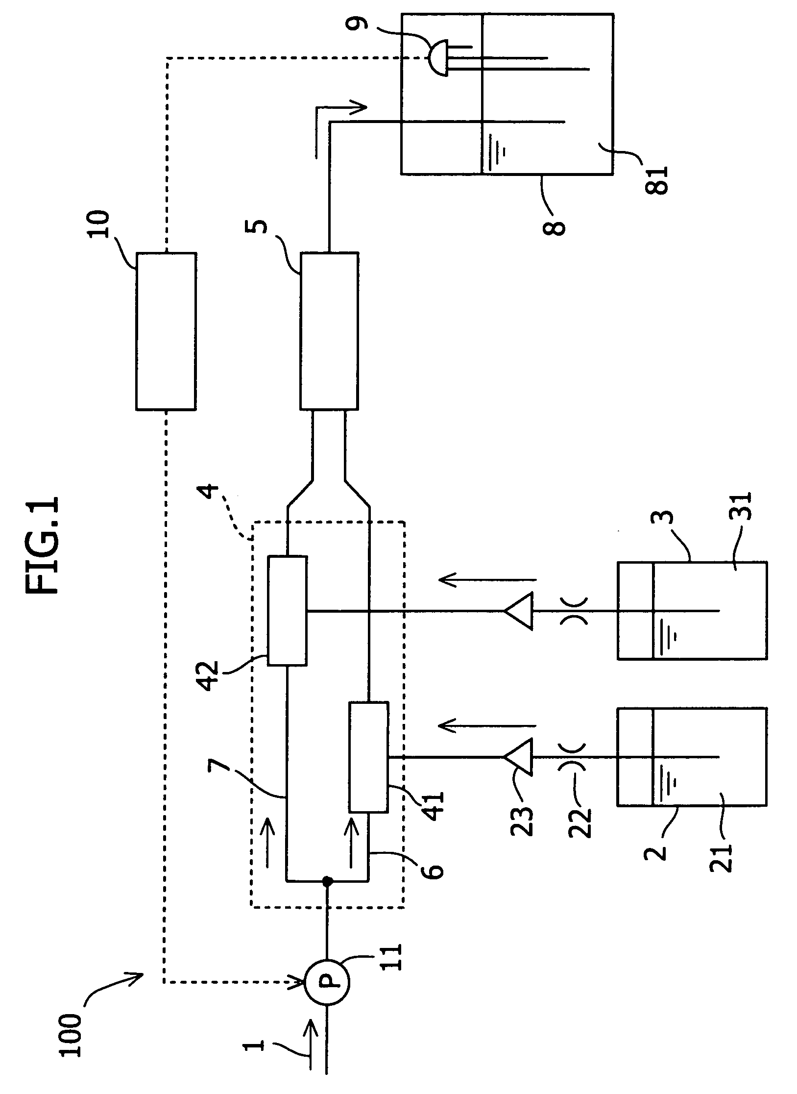
[0106]An embodiment of the present invention will be described. FIG. 1 is a schematic system view of an apparatus 100 for manufacturing sterilizing water in accordance with one embodiment of the present invention.

[0107]In the apparatus 100 for manufacturing sterilizing water, raw water 1 is sucked and supplied under pressure by a suitable pump 11, and to the supplied raw water 1, an acid solution 21 is fed from an acid tank 2 to form an acidic water, and further a chlorine-based solution 31 is fed from a chlorine-based solution tank 3, by which sterilizing water is manufactured. The configuration is such that the quantity of feeding of the acid solution 21 is controlled by a flow rate regulating portion 22, and when the water flow is shut off by a check valve 23, a flow path 6 is isolated from the acid tank 2.

[0108]The raw water 1 is not subject to any special restriction, and pure water, city water, river water, underground water, and the like are suitably used according to the app...

second embodiment

[0125]Another embodiment of the present invention will be described. FIG. 6 is a schematic system view of an apparatus 101 for manufacturing sterilizing water in accordance with another embodiment of the present invention.

[0126]In the apparatus 101 for manufacturing sterilizing water, as in the apparatus 100 for manufacturing sterilizing water, the raw water 1 is sucked and supplied under pressure by the suitable pump 11, and to the supplied raw water 1, the acid solution 21 is fed from the acid tank 2 to form the dilute acid solution, and further the chlorine-based solution 31 is fed from the chlorine-based solution tank 3, by which sterilizing water is manufactured.

[0127]In this embodiment, unlike the above-described first embodiment, the raw water 1 flows in a series of flow path, not in plural flow paths. The acid solution 21 and the chlorine-based solution 31 are fed in this order to the raw water 1 flowing in the flow path. The acid solution 21 is fed to the raw water in a fee...

third embodiment

[0136]Next, the case where the concentration of chlorine-based solution is changed in the apparatus for manufacturing sterilizing water in accordance with the present invention will be explained.

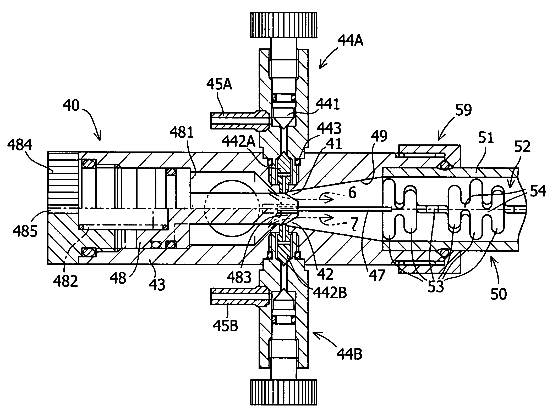
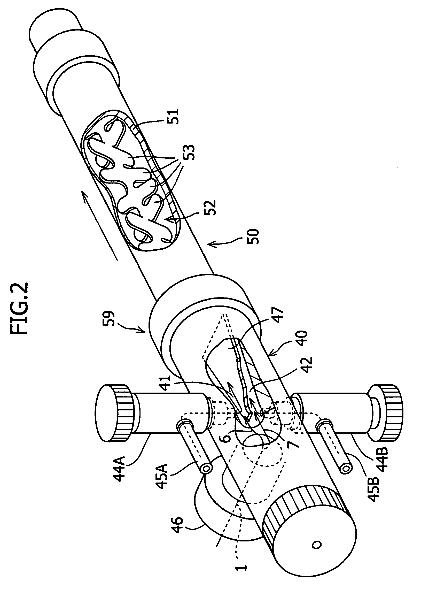
[0137]In this embodiment, the properties of sterilizing water were studied by changing the concentration of chlorine-based solution by changing the dilution ratio thereof. In the present invention, as the chlorine-based solution before dilution, a sodium hypochlorite solution with a concentration of 12% was used, and as the apparatus for manufacturing sterilizing water, an apparatus having a system shown in FIG. 1 and being provided with the feeder and mixer of the examples shown in FIGS. 2 and 3 was used.

[0138]The final concentration of chlorine-based solution and the sterilization power at each concentration were evaluated for each dilution ratio as given in Table 1.

[0139]

TABLE 1Dilution ratio (times)120001200400300 100Concentration (ppm)  10 1003004001200Sterilization powerNormalEnoughEno...


PUM

PropertyMeasurementUnit
pressureaaaaaaaaaa
pressureaaaaaaaaaa
heightaaaaaaaaaa

Abstract

There is provided an apparatus for manufacturing sterilizing water, in which the sterilization power of a chlorine-based solution consisting of sodium hypochlorite or chlorine dioxide or a mixture thereof is fully achieved while the generation of chlorine gas is restrained, and desired sterilizing water is manufactured by properly feeding and mixing three liquids of water, an acid solution, and a chlorine-based solution at a fully controlled concentration. In the apparatus for manufacturing sterilizing water of some aspect of the present invention, after both acid solution and chlorine-based solution have been diluted with raw water in a feeder, the dilute solutions can be mixed with each other by a mixer.

Description

RELATED APPLICATIONS[0001]The present application is a National Phase application of PCT / JP03 / 05767 filed on May 8, 2003, which claims priority from Japanese Patent Application Numbers 2002-134785 filed May 10, 2002; 2002-319214 filed Nov. 1, 2002; and 2002-376382 filed Dec. 26, 2002, the disclosures of which are incorporated herein by reference.FIELD OF THE INVENTION[0002]The present invention relates to an apparatus for manufacturing sterilizing water used for food processing, stock raising, medical care, and the like. More particularly, it relates to an apparatus for manufacturing sterilizing water that accomplishes chlorination by sodium hypochlorite solution or chlorine dioxide solution.BACKGROUND OF THE INVENTION[0003]Conventionally, sodium hypochlorite solution having sterilizing properties has been used as a bleaching agent or a mold remover. Also, the use of chlorine dioxide for sterilization of city water has been studied. Such sterilizing water in which the concentration ...

Claims


Application Information

Patent Timeline
Patent Type & Authority Patents(United States)
IPC IPC(8): B01F5/04B01F5/06A61L2/18B01F3/08B01F5/00B01F15/00B01F15/04C02F1/00C02F1/50C02F1/66C02F1/68C02F1/76G01F1/22G05D11/00G05D11/02G05D11/13
CPCA61L2/18G05D11/131B01F3/088B01F5/0415B01F5/0617B01F5/0619B01F15/00207B01F15/0412C02F1/50C02F1/686C02F1/76G01F1/22G05D11/006B01F3/0861B01F2005/0435B01F2005/0621B01F2005/0637C02F1/66C02F2103/026C02F2209/42C02F2301/043C02F2303/04Y10T137/87595B01F23/45B01F23/49B01F25/312511B01F25/3121B01F25/43151B01F25/43161B01F25/4317B01F25/431972B01F35/213B01F35/83
Inventor SAKATA, YUOKAZAKI, TOSHIOIKEDA, TOSHIZUMI
Owner FAMILY LIFE
Why Eureka
Try Eureka