Optical distance measuring apparatus

a technology of optical distance measurement and measuring apparatus, which is applied in the direction of distance measurement, measurement gauges, instruments, etc., can solve the problems of difficult to eliminate background light noise, circuit configuration becomes complicated, and the voltage waveform is easily delayed in phase under the influence of an environment, so as to achieve high accuracy of distance measurement

Inactive Publication Date: 2008-08-26
SHARP KK
View PDF6 Cites 30 Cited by
  • Summary
  • Abstract
  • Description
  • Claims
  • Application Information

AI Technical Summary

Benefits of technology

[0016]It is therefore a feature of the exemplary illustrative embodiment presented herein to provide an optical distance measuring apparatus having a high accuracy of distance measurement even under an environment where background light is strong.

Problems solved by technology

Under such a circumstance, it is very difficult to eliminate the noise attributable to the background light to extract the signal light pulse appropriately.
Furthermore, a voltage waveform easily delays in phase under the influence of an environment (mainly a temperature environment), etc.
In this case, the circuit configuration becomes very complicated, and will eventually lead to increase in manufacturing cost.
However, the distance image sensor disclosed in JP 2004-294420A has a problem as described below.

Method used


Image

  • Optical distance measuring apparatus
  • Optical distance measuring apparatus
  • Optical distance measuring apparatus

Examples


first embodiment

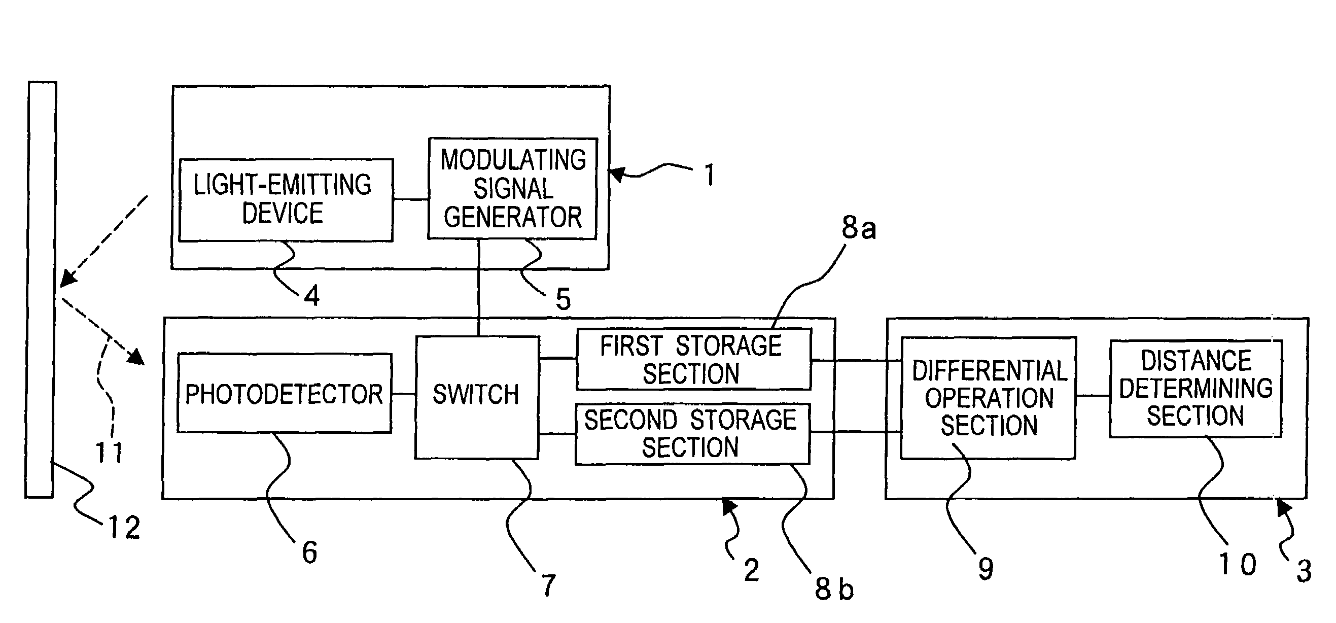
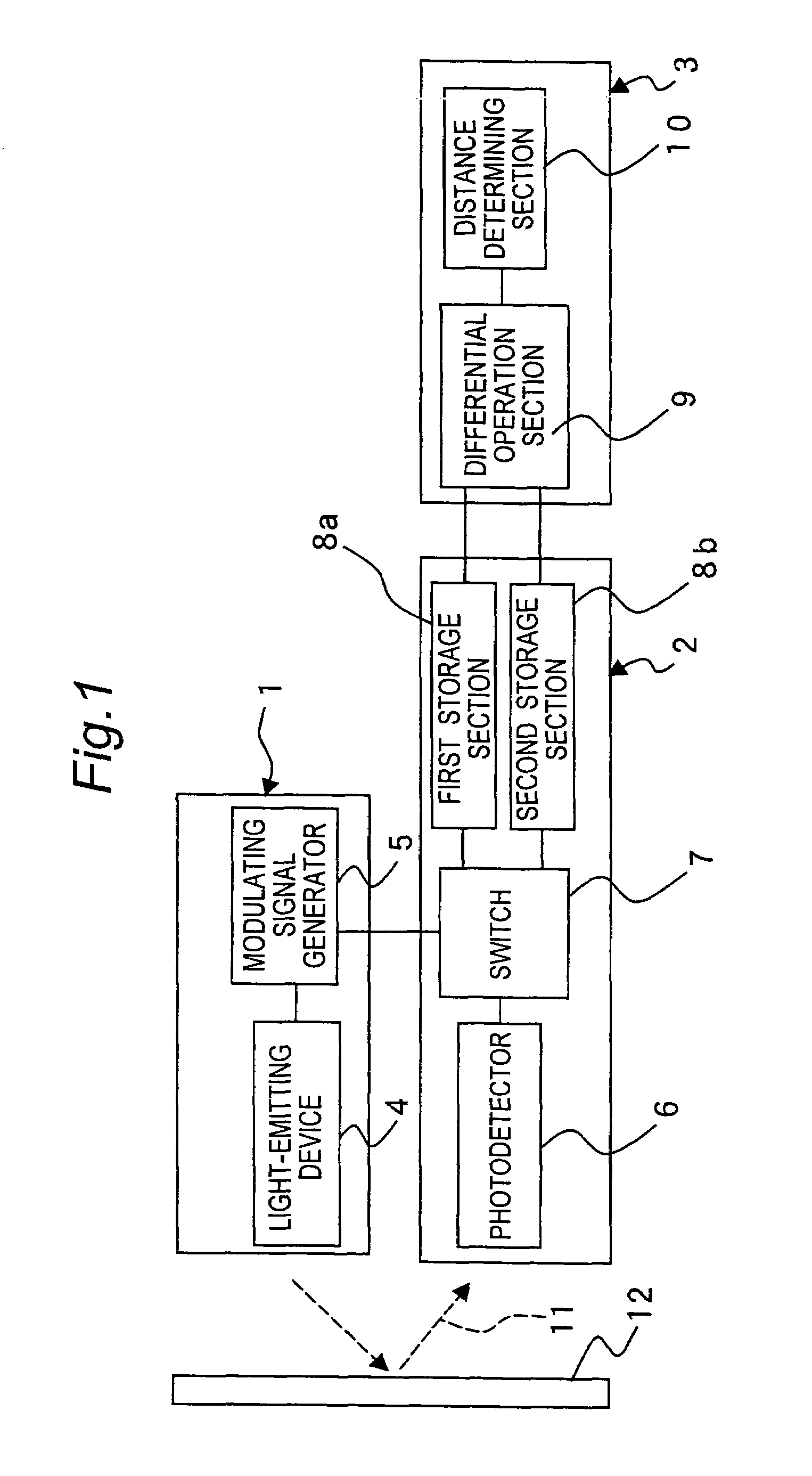
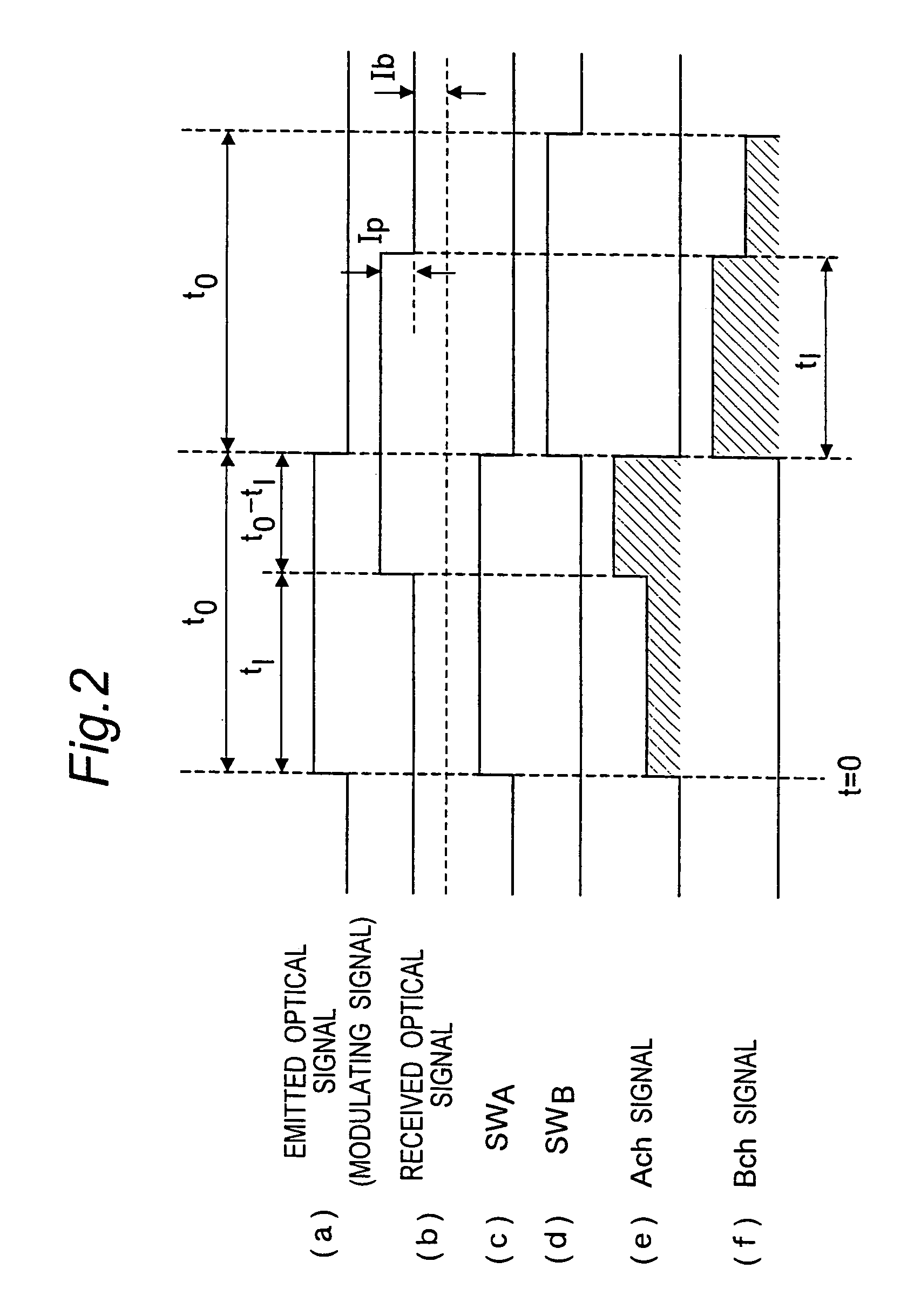
[0142]FIG. 1 is a block diagram of an optical distance measuring apparatus of a first example embodiment, and FIG. 2 is a timing chart depicting the operation of the optical distance measuring apparatus shown in FIG. 1. Outline of the optical distance measuring apparatus according to the present techology will be described with reference to FIGS. 1 and 2.

[0143]The optical distance measuring apparatus has, as shown in FIG. 1, a transmitter 1 for emitting an optical beam 11 as an optical signal to an object to be measured 12, a receiver 2 for receiving the optical beam 11 reflected by the object 12, and a signal processing section 3 for processing a signal from the receiver 2.

[0144]The transmitter 1 has a light-emitting device 4 for emitting an optical signal which is synchronized with a modulating signal having a predetermined repetition frequency, and a modulating signal generator 5 for outputting the modulating signal to the light-emitting device 4.

[0145]The receiver 2 has a photod...

second embodiment

[0156]FIG. 3 is a block diagram of an optical distance measuring apparatus of a second example embodiment, and FIG. 4 is a timing chart depicting the operation of the optical distance measuring apparatus. Outline of the optical distance measuring apparatus of this embodiment will be described with reference to FIGS. 3 and 4. In FIG. 3, the same components as those in FIG. 1 are denoted by the same symbols.

[0157]This optical distance measuring apparatus has, as shown in FIG. 3, a transmitter 1 for emitting an optical beam 11 as an optical signal to an object 12 to be measured, a receiver 2 for receiving the optical beam 11 reflected by the object 12, and a signal processing section 3 for processing signals from the receiver 2.

[0158]The transmitter 1 has a light-emitting device 4 for emitting an optical signal which is synchronized with a modulating signal having a predetermined repetition frequency, and a modulating signal generator 5 for outputting the modulating signal to the light...

third embodiment

[0177]Next, FIG. 5 shows a block diagram depicting the configuration of an optical distance measuring apparatus of a third example embodiment wherein the modulating signal is a sinusoidal wave, and its timing chart is shown in FIG. 6. In FIG. 5, same components as those in FIG. 1 are denoted by the same symbols.

[0178]This optical distance measuring apparatus has, as shown in FIG. 5, a transmitter 1 for emitting an optical beam 11 as an optical signal to an object 12 to be measured, a receiver 2 for receiving the optical beam 11 reflected by the object 12, and a signal processing section 3 for processing a signal from the receiver 2.

[0179]The transmitter 1 has a light-emitting device 4 for emitting an optical signal which is synchronized-with a modulating signal having a predetermined repetition frequency, and a modulating signal generator 5 for outputting a modulating signal to the light-emitting device 4.

[0180]The receiver 2 has a photodetector 6 for receiving an optical beam 11 re...


PUM


Abstract

In an optical distance measuring apparatus, a transmitter has a light-emitting device emitting an optical signal synchronized with a modulating signal having a predetermined repetition frequency, and a modulating signal generator outputting the modulating signal to the light-emitting device. A receiver has a photodetector receiving an optical beam reflected by an object to be measured and converting it to an electrical signal, a switch receiving the signal from the modulating signal generator and alternately choosing two channels for the electrical signal with a predetermined timing, and first and second storage sections storing electrical signals on the two channels. A signal processing section has a differential operation section performing a differential operation on electrical signals stored in the first and second storage sections, and a distance determining section determining a distance to the object on the basis of the result of the differential operation of the differential operation section.

Description

[0001]This nonprovisional application claims priority under 35 U.S.C. §119(a) on Patent Application Nos. 2005-313784 and 2005-327510 filed in Japan on Oct. 28, 2005 and Nov. 11, 2005, respectively, the entire contents of which are hereby incorporated by reference.BACKGROUND OF THE INVENTION[0002]The present invention relates to an optical distance measuring apparatus for measuring a transit time of light between a time when the light is emitted and a time when the light reflected by an object to be measured is detected by a photodetector, to detect the distance to the object.[0003]A so-called time-of-flight (TOF) method which is a method of measuring a time required for light to travel to an object and back to calculate the distance to the object has been widely known as a distance measuring method. This distance measuring method is a method of measuring a time Δt required for light to travel to an object and back and calculating the distance L to the object using the following Eq. ...

Claims


Application Information

Patent Timeline
Patent Type & Authority Patents(United States)
IPC IPC(8): G01B3/36
CPCG01S7/493G01S7/4915G01S7/4913G01S17/36
Inventor WADA, HIDEOWATANABE, NOBUHISATAMINAGA, TAKAYUKI
Owner SHARP KK
Why Eureka
Try Eureka