Defect inspection method and apparatus for transparent plate-like members

a technology of transparent plate and inspection method, which is applied in the direction of measurement devices, instruments, scientific instruments, etc., can solve the problems of difficult to distinguish between defects and pseudo defects just by light scattering directivity, and the thickness direction of transparent plate materials is difficult to identify the positions of defects, so as to achieve the effect of not reducing inspection performan

Inactive Publication Date: 2008-09-02
ASAHI GLASS CO LTD
View PDF8 Cites 19 Cited by
  • Summary
  • Abstract
  • Description
  • Claims
  • Application Information

AI Technical Summary

Benefits of technology

[0020]As described above, according to the present invention, by using images of defect candidates appearing on or in the main surface side and the rear surface side of a transparent plate material, defects (such as bubbles, scratches, and foreign matters) and pseudo defects (such as dust and grime) can be distinguished to realize an online defect inspection. In addition, the present invention has the advantages that the position of a defect can be correctly identified in the thickness direction of the transparent plate material, that inspection performance is not reduced depending on the size of the transparent plate material, and that transparent plate materials with a wider range of thicknesses can be inspected compared with the edge light method. Furthermore, since a transparent plate material is not required to have a smooth end face in the present invention, the present invention can be also applied to sheet-glass continuous forming processes, such as the float process.

Problems solved by technology

However, since light-scattering directivity differs depending on the types of defects, and since pseudo defects also exhibit various light-scattering directivity, it is difficult to distinguish between defects and pseudo defects just by light-scattering directivity.
In addition, since the method disclosed in JP-A-8-201313 uses a transmission optical system, it is difficult to identify the positions of defects in the thickness direction of the transparent plate materials.
Therefore, when cameras are disposed at a main surface side and a rear surface side of the transparent plate material, only defects can be detected.

Method used


Image

  • Defect inspection method and apparatus for transparent plate-like members
  • Defect inspection method and apparatus for transparent plate-like members
  • Defect inspection method and apparatus for transparent plate-like members

Examples


examples

[0079]Next, examples of the present invention will be described. It should be clearly understood that these examples do not limit the present invention.

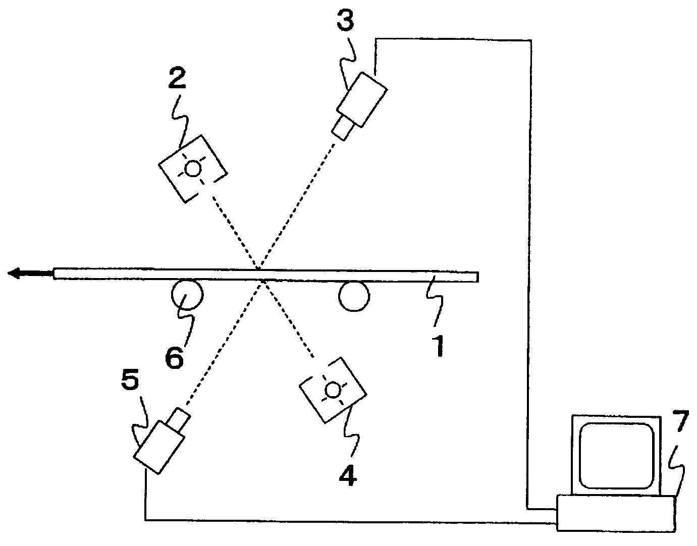
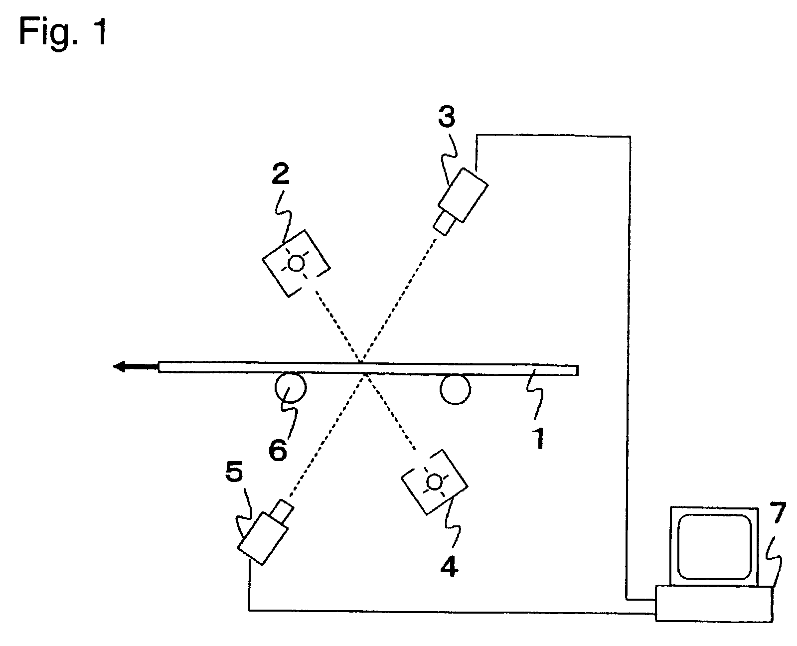
[0080]The utility of the present invention was tested by using a glass substrate having a thickness of 0.7 mm for an LCD panel (hereinafter called the glass substrate) as a transparent plate material, which will be described below in detail. According to the basic structure shown in FIG. 1, reflective bright-field optical systems were prepared, using two line sensor cameras and two linear light sources that employed fluorescent lights, and the systems were arranged above and below the glass substrate. The angle formed between the optical axis of each line sensor camera and the normal line of the glass substrate was set to 30 degrees. Conveying rollers 6 conveyed the glass substrate at a conveying speed of 100 mm / s.

[0081]The line sensor cameras continuously performed scanning and took images in the vicinities of defects and pseudo def...


PUM

PropertyMeasurementUnit
thicknessaaaaaaaaaa
angleaaaaaaaaaa
conveying speedaaaaaaaaaa

Abstract

A defect inspection method and apparatus for a transparent plate material for detecting a bubble, a scratch, a foreign matter, and another defect existing on or in the transparent plate material including regarding a defect candidate as a defect, when the defect candidate is located in both first and second images, and regarding the defect candidate as a pseudo defect, when the defect candidate is located in only one of the first and second images.

Description

TECHNICAL FIELD[0001]The present invention relates to a defect inspection method and a defect inspecting apparatus for a transparent plate material, and more particularly, to a defect inspection method and apparatus for glass substrates used for various types of display units (such as liquid crystal display (LCD) units, plasma display panel (PDP) units, electroluminescence (EL) units, field emission display (FED) units, or LCD projection TV sets), for a glass base plate for automobiles and other vehicles, and for sheet glass for buildings.BACKGROUND ART[0002]In the defect inspection for transparent plate materials, it is necessary to distinguish defects, such as bubbles, foreign matters, or scratches, from pseudo defects that do not affect the quality of the transparent plate materials, such as dust and grime. Depending on the positions of defects (whether defects are located on a main surface, in the inside, or on a rear surface) in the transparent plate materials and the depths of...

Claims


Application Information

Patent Timeline
Patent Type & Authority Patents(United States)
IPC IPC(8): G01N21/00
CPCG01N21/896G01N2021/8967G01N2021/8908
Inventor SONDA, YOSHIYUKI
Owner ASAHI GLASS CO LTD
Why Eureka
Try Eureka