Method and apparatus for signal decoding in a diversity reception system with maximum ratio combining

Inactive Publication Date: 2008-09-02
VIXS SYSTEMS INC
View PDF14 Cites 26 Cited by
  • Summary
  • Abstract
  • Description
  • Claims
  • Application Information

AI Technical Summary

Benefits of technology

[0031]An embodiment of the present invention can comprise an apparatus for decoding a multiple received radio frequency (RF) signal. The apparatus can comprise a processing module and a memory operably coupled to the processing module, wherein the memory includes operational instructions that cause the processing module to perform one or more of the method steps described above. The embodiments of the method and apparatus for decoding a multiple

Problems solved by technology

Factory floor workers can access part and process specifications without wired network connections, which may be impractical on the factory floor.
In such a receiver baseband processor, the slicing module is a critical component not only from an accuracy standpoint (e.g., errors in the estimation information produces errors in the resulting data), but also from an efficiency standpoint.
As such, even though a soft slicing module generally provides a 3 dB signal-to-noise ratio improvement over a hard slicing module, it requires a significant amount of processing resources to produce the error values.
While communications standards, such as IEEE 802.11a, allow a single transmitting device to provide data to multiple receiving devices, the quality of data received by some receiving devices may be degraded.
As the SNR becomes too low for a particular data signal, the BER associated with a receiving device may be too high for the receiving device.
The transmission power associated with a data signal transmitted to a particular receiving device may be too low.
A signal may also be degraded due to interference from other data transmitters or other RF radiators.
Accordingly, other

Method used


Image

  • Method and apparatus for signal decoding in a diversity reception system with maximum ratio combining
  • Method and apparatus for signal decoding in a diversity reception system with maximum ratio combining
  • Method and apparatus for signal decoding in a diversity reception system with maximum ratio combining

Examples


Embodiment Construction

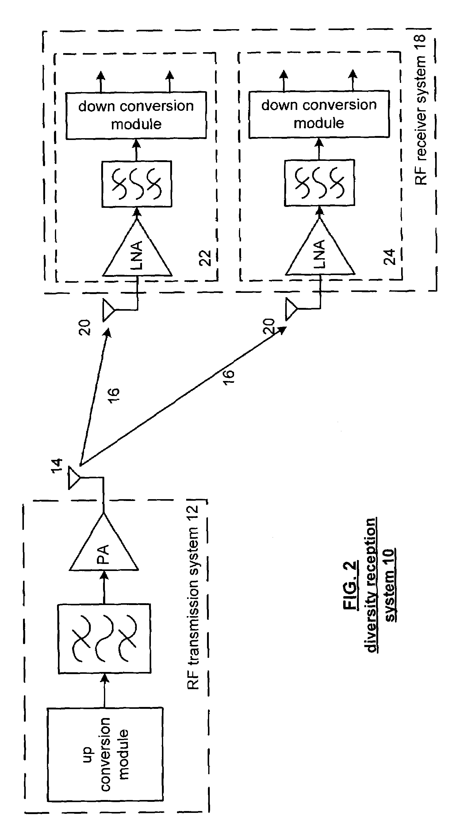
[0046]The present invention can be more fully described with reference to FIGS. 2 through 21. FIG. 2 is a high-level block diagram illustrating a generic diversity reception system 10, such as can be used to implement the various embodiments of the present invention. Diversity reception system 10 can be any diversity reception system as known to those familiar with the art. Diversity reception system 10 comprises a radio frequency (“RF”) transmission system 12, which can be any RF transmission system as known in the art, comprising an antenna 14 used to transmit data along RF channel 16. Diversity reception system 10 also includes an RF receiver system 18 for receiving the data transmitted on RF channel 16. Receiver system 18 can be any type RF diversity receiver system as known in the art and comprises, in this example, dual antennas 20 for receiving the data signal transmitted on RF channel 16. Dual antennas 20 each provide a separate version of the received data signal to their r...


PUM


Abstract

A method signal for decoding in a diversity reception system can include converting the received RF signal into a plurality of digital baseband signals; phase aligning the plurality of digital baseband signals to produce a plurality of phase aligned digital baseband signals; determining a plurality of error terms from the plurality of phase aligned digital baseband signals; one of which corresponding to one of the plurality of phase aligned digital baseband signals; determining a plurality of weighting factors for the plurality of error terms based on characteristics of the plurality of digital baseband signals, one of which corresponding to one of the plurality of error terms; applying the plurality of weighting factors to the plurality of error terms to produce a plurality of weighted error terms; summing the plurality of weighted error terms to produce an error term for decoding.

Description

[0001]This patent application is claiming priority under 35 USC §119(e) to provisionally filed patent application having the same title as the present patent application, having a serial number of 60 / 437,409, and a filing date of Dec. 31, 2002.TECHNICAL FIELD OF THE INVENTION[0002]This invention relates generally to radio frequency communication systems, and, more particularly, to a method and apparatus for radio frequency signal decoding with maximum ratio combining in a diversity reception system.BACKGROUND OF THE INVENTION[0003]Wireless communication has become increasingly important as a means of transferring information in all areas of society. Government, business and consumer markets have all benefited from the increasing sophistication and availability of wireless communication methods and devices. For example, the use of pagers, cellular telephones and wireless-capable personal digital assistants (“PDAs”) is now commonplace. Wireless communication is also used extensively i...

Claims


Application Information

Patent Timeline
IPC IPC(8): H04B7/10H04L27/00H04B7/08
CPCH04B7/0857
Inventor WALLACE, BRADLEY A.GIRARDEAU, JR., JAMES WARDKELTON, JAMES ROBERT
Owner VIXS SYSTEMS INC
Why Eureka
Try Eureka