Image tessellation for region-specific coefficient access

a region-specific coefficient and image compression technology, applied in the field of image data compression and handling, can solve the problems of large image files, large disc or storage space, and increasing complexity of imaging systems, and achieve the effect of large image files, large image files, and large image files

Inactive Publication Date: 2008-09-02
GE MEDICAL SYST INFORMATION TECH
View PDF37 Cites 28 Cited by
  • Summary
  • Abstract
  • Description
  • Claims
  • Application Information

AI Technical Summary

Problems solved by technology

A major challenge to further improvements in all image handling systems, from simple Internet browsers to PACS in medical diagnostic applications, is the handling of the large data files defining images.
While image files may be stored in raw and processed formats, many image files are quite large, and would occupy considerable disc or storage space.
The increasing complexity of imaging systems also has led to the creation of very large image files, typically including more data as a result of the useful dynamic range of the imaging system, the size of the matrix of image pixels, and the number of images acquired per examination.
In addition to occupying large segments of available memory, large image files can be difficult or time consuming to transmit from one location to another.
Moreover, current techniques do not offer sufficiently rapid compression and decompression of image files to satisfy increasing demands on system throughput rates and access times. Finally, alternative compression and decompression techniques do not offer the desired compression ratios, in combination with rapid compression and decompression in a client-server environment.
Another drawback of existing compression techniques is the storage, access and transmission of large data files even when a user cannot or does not desire to view the reconstructed image in all available detail.
For example, in medical imaging, extremely detailed images may be acquired and stored, while a radiologist or physician who desires to view the images may not have a view port capable of displaying the image in the resolution in which they are stored.
Thus, transmission of the entire images to a remote viewing station, in relatively time consuming operations, may not provide any real benefit and may slow reading or other use of the images.

Method used


Image

  • Image tessellation for region-specific coefficient access
  • Image tessellation for region-specific coefficient access
  • Image tessellation for region-specific coefficient access

Examples


Embodiment Construction

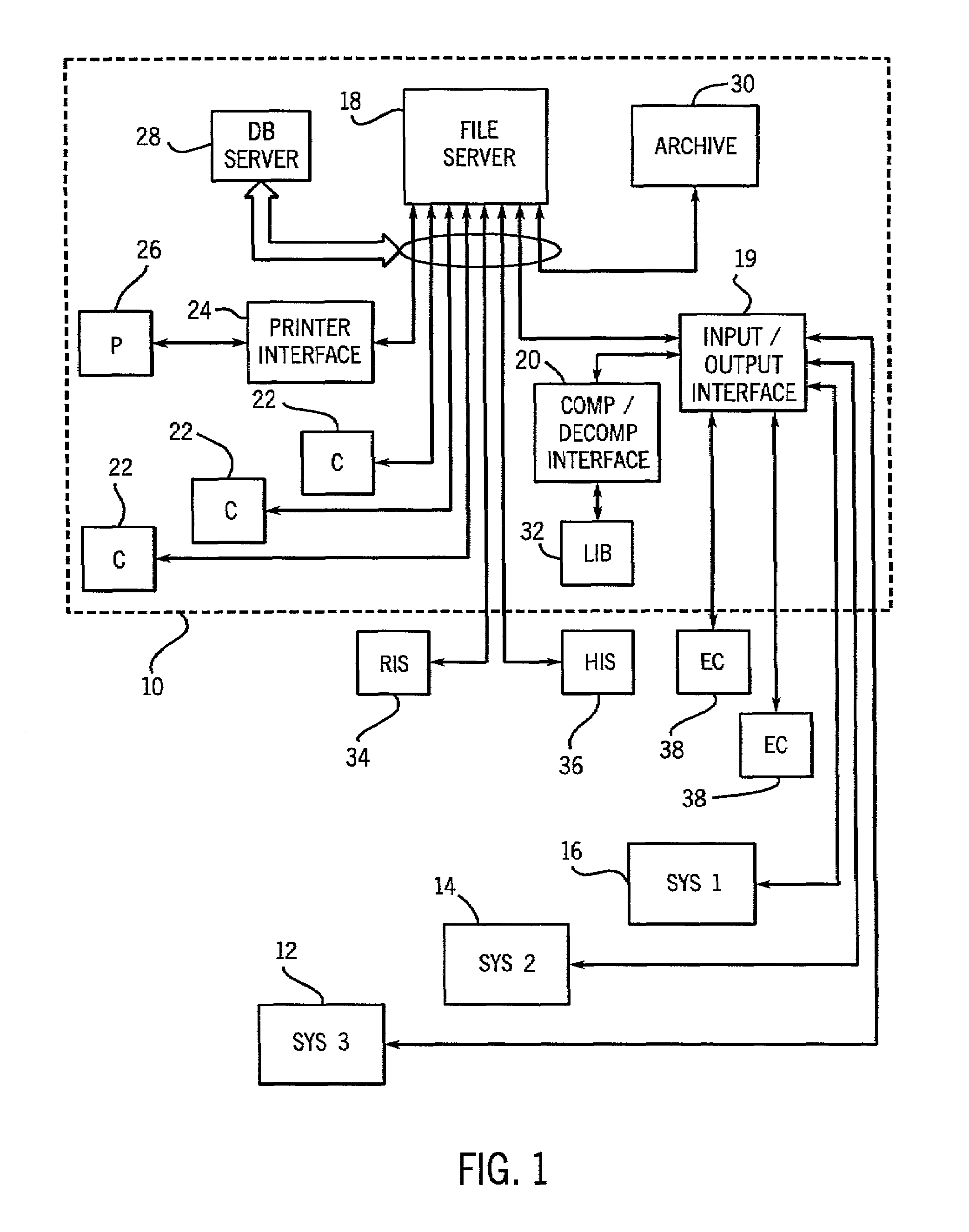
[0036]FIG. 1 illustrates an exemplary image data management system in the form of a picture archive and communication system or PACS 10 for receiving, compressing and decompressing image data. In the illustrated embodiment, PACS 10 receives image data from several separate imaging systems designated by reference numerals 12, 14 and 16. As will be appreciated by those skilled in the art, the imaging systems may be of various type and modality, such as magnetic resonance imaging (MRI) systems, computed tomography (CT) systems, positron emission tomography (PET) systems, radio fluoroscopy (RF), computed radiography (CR), ultrasound systems, and so forth. Moreover, the systems may include processing stations or digitizing stations, such as equipment designed to provide digitized image data based upon existing film or hard copy images. It should also be noted that the systems supplying the image data to the PACS may be located locally with respect to the PACS, such as in the same institu...


PUM


Abstract

The present technique addressably handles image data, which is decomposed and tessellated into a plurality of tessellated sub-band blocks. The tessellated sub-band blocks may be addressed by an array of indices, which identify specific data blocks of the image data by decomposition level and spatial coordinates of the tessellated sub-band blocks. Accordingly, a desired region of the image data at multiple resolutions can be identified and individually handled for storage, transmission, retrieval, and display. The desired region also can be reference marked based on the array of indices.

Description

CROSS REFERENCE TO RELATED APPLICATIONS[0001]The present is a Continuation-in-Part of patent application Ser. No. 09 / 716,603, filed Nov. 20, 2000 now U.S. Pat. No. 6,912,319, which is a Continuation-In-Part of patent application Ser. No. 09 / 448,950, filed on Nov. 24, 1999 now U.S. Pat. No. 6,633,674.FIELD OF THE INVENTION[0002]The present invention relates generally to the field of image data compression and handling. More particularly, the invention relates to a technique for addressing image data by image block indices for rapid transmission and selective handling of a desired area of interest.BACKGROUND OF THE INVENTION[0003]A wide range of applications exist for image data compression. Digitized images may be created in a variety of manners, such as via relatively simple digitizing equipment and digital camera, as well as by complex imaging systems, such as those used in medical diagnostic applications. Regardless of the environment in which the image data originates, the digita...

Claims


Application Information

Patent Timeline
Patent Type & Authority Patents(United States)
IPC IPC(8): G06K9/36G06T3/40G06T9/00H04N7/26H04N19/593H04N21/2343H04N21/258H04N21/2662H04N21/6373
CPCG06T3/4092H04N19/184H04N21/25808H04N21/2662H04N21/6373H04N19/105H04N19/70H04N19/46H04N19/63H04N19/61H04N19/593H04N19/103H04N19/127H04N19/132H04N19/136H04N19/14H04N19/186H04N19/146H04N19/156H04N19/17H04N21/234327H04N19/10H04N19/13
Inventor SIROHEY, SAAD A.BARNES, ROBERT D.DE VAAN, JANMUKHOPADHYAY, SUDIPTAWHEELER, FREDERICK WILSON
Owner GE MEDICAL SYST INFORMATION TECH
Why Eureka
Try Eureka