System and method for scaling performance of a data processing system

a data processing system and scaling technology, applied in the field of data processing systems, can solve the problems of exceeding the processing power of the available computer resources, and the time it takes to process the data is short, and the processing power required to handle is not enough

Active Publication Date: 2008-09-02
UNISYS CORP
View PDF6 Cites 35 Cited by
  • Summary
  • Abstract
  • Description
  • Claims
  • Application Information

AI Technical Summary

Benefits of technology

[0023]The inventive system and method provides several benefits over the prior art solutions. Customers are allowed to utilize any available hardware, which is automatically scaled to provide up to the maximum purchased performance level. The customer may therefore modify the system configuration to compensate for any hardware faults so that system throughput will not be affected by such faults. Moreover, the configuration may be adjusted to take into account the types of work being processed, thereby maximizing system throughput. In one embodiment, the SCPF may perform configuration modification automatically based on some trigger condition such as time of day, or the type of work available for processing. In all cases, the performance of each IP is automatically scaled so that the overall system delivers the purchased level of performance.
[0025]Another embodiment of the invention provides a method of controlling the performance of a data processing system. This method includes providing a predetermined level of performance for use on the data processing system, allowing the data processing system to be configured in any selected one of multiple available configurations, and scaling the performance of the selected configuration so that the data processing system provides the predetermined level of performance.

Problems solved by technology

Many growing businesses are challenged with ensuring that their data processing systems keep pace with expanding demands.
Another challenge facing many businesses is that of predicting and handling the peak loads that will be required to keep up with the day-to-day operations.
For example, if there is a delay in gathering year-end data, there may be little time to process the data before the results must be published or otherwise released.
The processing power required to handle such year-end data on such short notice may exceed the processing power of the available computer resources.
In another example, e-commerce servers may experience severe peak loads during certain times of the year, such as the Christmas season.
The extent of these peak loads is also often difficult to predict.
This can be expensive, and is not desirable if the additional systems are only required to address peak loads that exist during relatively short time periods.
However, system updates may necessitate the termination of normal processing activities so that the system can be powered down or otherwise placed in a state that accommodates maintenance.
This can significantly disrupt the operations of the business.
Moreover, updating a system to take into account peak demand is undesirable if this worst-case scenario rarely occurs.
If one of these identified IPs encounters some type of hardware problem, the customer is not allowed to instead employ one of the other available processors that is not specified by the key.
Thus, encountered hardware problems may result in degraded throughput.
Thus, the customer may not always be obtaining peak performance from the enabled resources.
Prior art partitionable keys do not account for system characteristics.
This is true because of the loss of throughput that occurs when data must be shared between two caches of the same partition.
Because the partitionable keys do not take into account such architectural considerations, the customer may not always be obtaining peak performance from the enabled resources.
Additionally, since one partitioning configuration may provide more processing power than another configuration, the keys are difficult to price fairly.

Method used


Image

  • System and method for scaling performance of a data processing system
  • System and method for scaling performance of a data processing system
  • System and method for scaling performance of a data processing system

Examples


Embodiment Construction

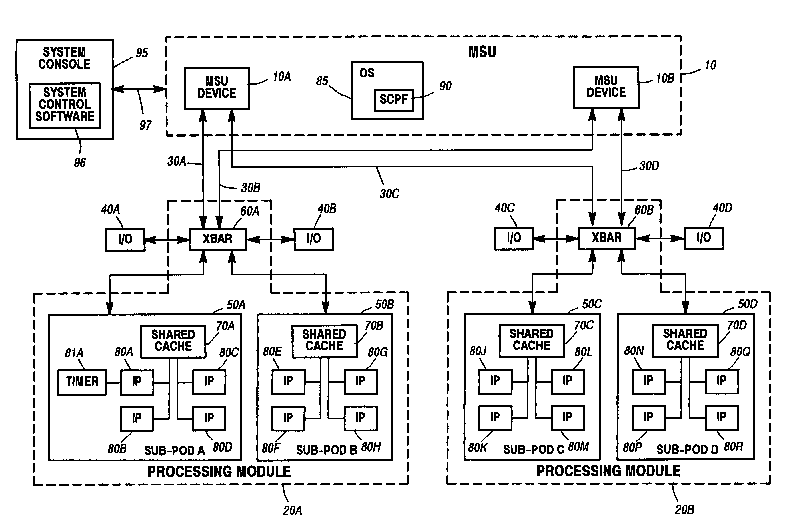
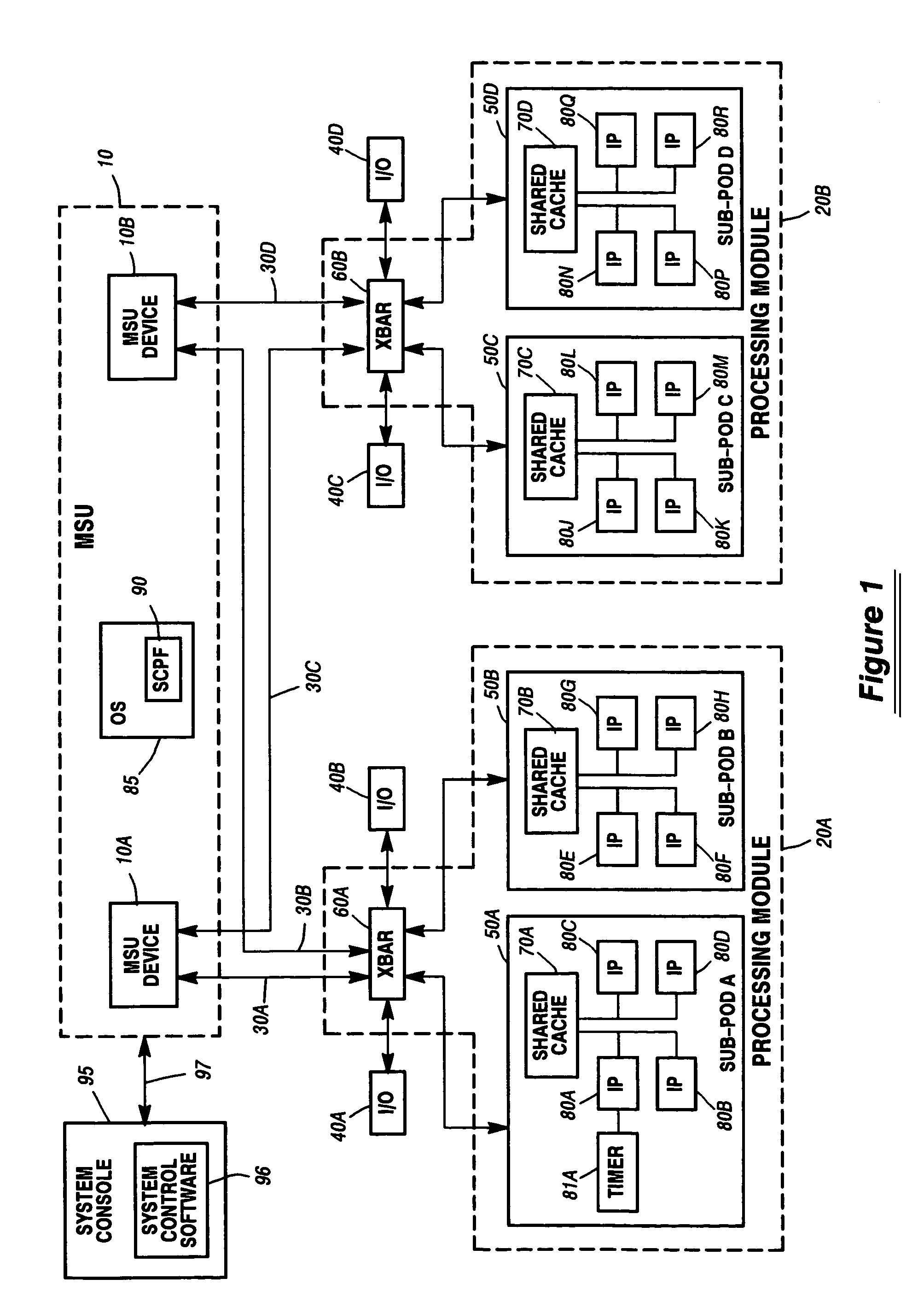
[0039]FIG. 1 is a block diagram of an exemplary system that may employ the current invention. This system includes a Memory Storage Unit (MSU) 10 (shown dashed) which provides the main memory facility for the system. The MSU includes one or more MSU devices individually shown as MSU 10A and MSU 10B, which each contains a predetermined portion of the memory space of the system. Many more MSU devices may be included within a full configuration.

[0040]The system further includes Processing mODules (PODs) 20A and 20B (shown dashed), which provides the processing capability for the system. A greater or lesser number of PODs may be included in the system than are shown in FIG. 1. In one embodiment, up to four PODs are included in a fully populated system.

[0041]Each of the PODs is coupled to each of the MSU devices via a dedicated, point-to-point connection referred to as an MSU Interface (MI), individually shown as MIs 30A through 30D. For example, MI 30A couples POD 20A to MSU device 10A,...


PUM


Abstract

A system and method for scaling the performance of a data processing system is disclosed. According to one method, a level of system performance is purchased for use with the data processing system. This purchased performance level is described in Millions of Instructions Per Second (MIPS) or a similar unit of measure. A system administrator selects which resources within the data processing system will be enabled, as well as how those resources will be configured. The enabled system resources will include one or more instruction processors. The performance of each of the enabled processors is then scaled to achieve the purchased system performance level. Performance scaling is performed in a manner that takes into account characteristics associated with the selected configuration as well as the system architecture.

Description

REFERENCE TO CO-PENDING APPLICATIONS[0001]The following commonly assigned co-pending applications have some subject matter in common with the current application:[0002]“Authorization Key System for Selectively Controlling the Performance of a Data Processing System”, Ser. No. 09 / 676,162 filed Sep. 29, 2000, and which is incorporated herein by reference in its entirety,[0003]Ser. No. 10 / 744,685 entitled “System and Method for Metering the Performance of a Data Processing System” filed on even date herewith.[0004]Ser. No. 10 / 744,040 entitled “Method and System for Economic Valuation in Partitioned Computer Systems”, filed on even date herewith.FIELD OF THE INVENTION[0005]The current invention relates generally to data processing systems, and more particularly to methods and apparatus for selectively controlling the performance level of data processing systems.BACKGROUND OF THE INVENTION[0006]Many growing businesses are challenged with ensuring that their data processing systems keep p...

Claims


Application Information

Patent Timeline
Patent Type & Authority Patents(United States)
IPC IPC(8): G06F9/46
CPCG06F21/71G06F9/5077
Inventor HANCOCK, PETER J.HANSEN, LEE B.LENZ, DANIEL J.MIKKELSEN, HANS C.TANNING, RONALD S.
Owner UNISYS CORP
Why Eureka
Try Eureka