Spray gun with pressure display

a pressure display and spray gun technology, applied in the field of spray guns, can solve the problems of wasting resources, adding wastes, and rarely using pressure gauges in actual spray coating, and achieves the effects of reducing paint consumption, reducing waste, and reducing was

Inactive Publication Date: 2008-09-09
ANEST IWATA CORP
View PDF16 Cites 31 Cited by
  • Summary
  • Abstract
  • Description
  • Claims
  • Application Information

AI Technical Summary

Benefits of technology

[0012]Accordingly, the present invention has an object to overcome the above-mentioned drawbacks of the related art by providing a spray gun usable with an accurate, easy-to-view pressure gauge which allows a spray coating of a stable and high quality, and can eliminate poor coating, minimize the paint consumption and prevent environmental pollution.
[0013]It is required that the pressure gauge used with the spray gun should be able to provide a stable pressure indication, have a long service life, be usable without any adverse influence on the shape and operability of the existent spray gun and permit the user to simply check an air pressure used in the spray gun.

Problems solved by technology

However, the pressure gauge is rarely used in actual spray-coating because its weight and size are not acceptable in the routine paint spraying jobs.
However, since the pressure gauge has to be designed smaller for installation to a spray gun which is normally not so large, such a pressure gauge is not satisfactory with respect to accuracy and durability in the operating environments.
When the service life of the driving cell has expired, the pressure gauge itself has to be discarded and replaced with a fresh one, which will lead to wasting of resources and addition of wastes.
However, the pressure gauge thus used on the spray gun will add to the size and weight of the spray gun, which will cause increased fatigue of the user of the spray gun and will adversely affect the operability of the spray gun itself.

Method used


Image

  • Spray gun with pressure display
  • Spray gun with pressure display
  • Spray gun with pressure display

Examples


Embodiment Construction

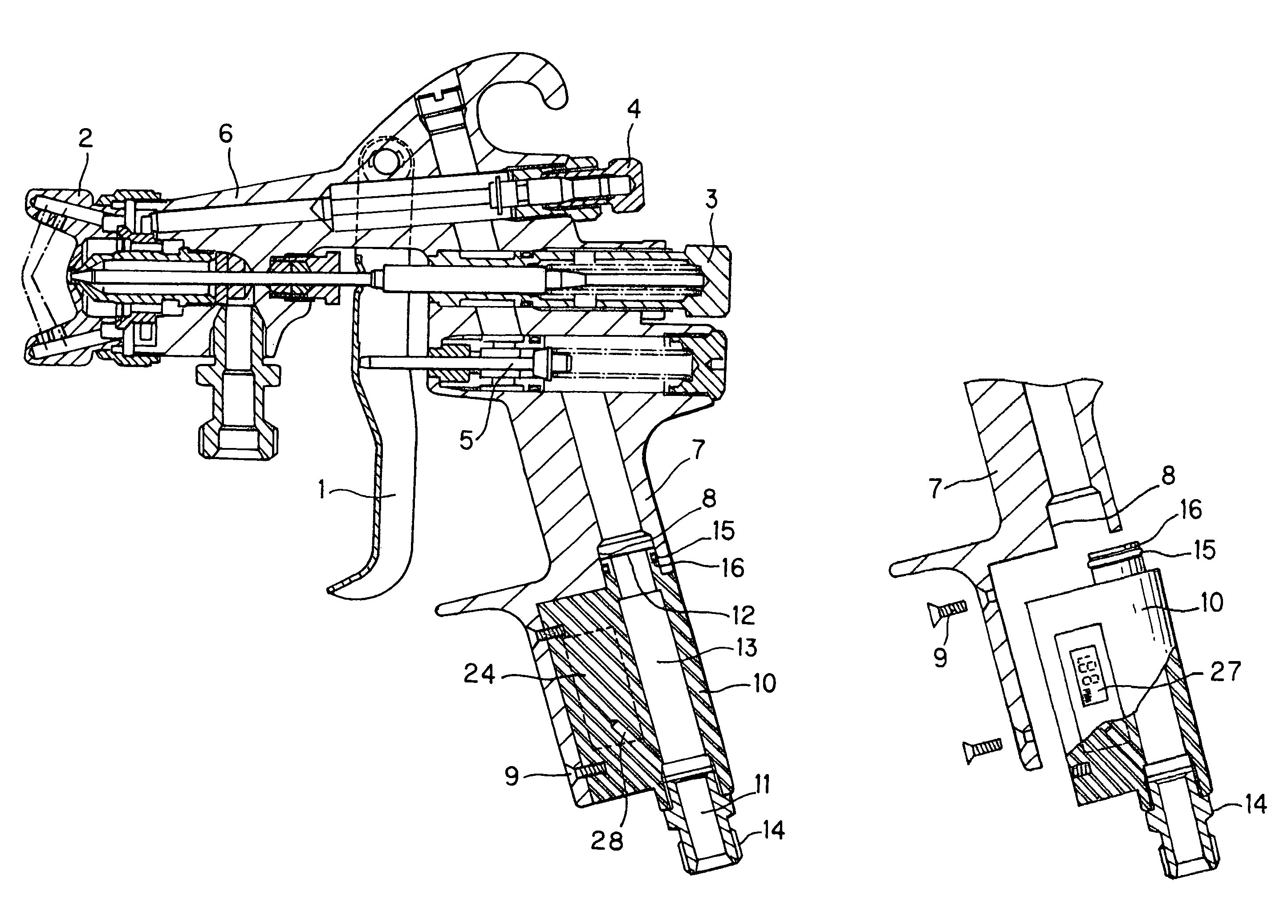
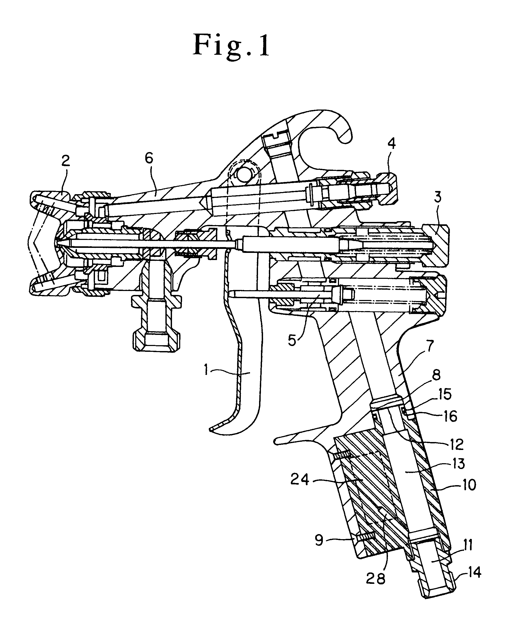
[0032]Referring now to FIG. 1, there is schematically illustrated in the form of a sectional view the spray gun according to an embodiment of the present invention. The spray gun is of a manual type operated by a trigger 1. As shown, the spray gun includes a body and the spray gun body includes a gun barrel 6 having an atomization air cap 2, paint supply adjuster 3, spray pattern adjuster 4 and an air valve 5, and a grip 7 extending backward and downward from the gun barrel 6. A pressure indication unit 10 is removably fixed to the lower end of the grip 7, and thus forms a part of the grip 7.

[0033]The pressure indication unit 10 has a compressed air intake 11 formed at the lower end thereof. The compressed air intake 11 communicates with a central air channel 13 extending to a portion 12 for coupling to the spray gun body, formed at the upper end of the pressure indication unit 10. The pressure indication unit 10 is externally threaded (indicated at a reference 14) on the outer surf...


PUM


Abstract

A spray gun with pressure display for applying paint onto a painted object by atomizing the paint with compressed air. A pressure indicating device includes a digitally displayed pressure sensor (25), a pressure transducer part (24), and a display part (27) unitized with each other. The pressure indicating device is detachably installed on a spray gun body, and adapters (21, 22) without a pressure indication function are detachably fitted to the spray gun body according to the shape of the body grip part so that the presence or absence of the pressure indication function can be selected before use. The spray gun can be used under controlled conditions by allowing a worker to detect an air pressure at hand during spraying operation since the spraying air pressure largely affects paint finish as well as dispersion of atomized paint.

Description

BACKGROUND OF THE INVENTION[0001]1. Technical Field[0002]The present invention relates to a spray gun usable with a module including a removable, easy-to-view, high-accuracy digital pressure gauge being installed in the spray gun as necessary.[0003]2. Description of Related Art[0004]The air spray gun uses compressed air to atomize a paint for spraying an object to be coated. To assure a stable quality of painting with the spray gun, it is necessary to always monitor and control the pressure of spraying compressed air. There are available some spray guns in which the spraying air pressure can be checked by the user operating the spray gun.[0005]In the spray coating, both the quality of the finished coating and scattering of the paint mist greatly depend upon the spraying air pressure used in the air spray gun to spray paint on an object. Namely, it is well known that a higher air pressure will provide an increased energy for spraying and a finer atomization of the paint, which has ge...

Claims


Application Information

Patent Timeline
Patent Type & Authority Patents(United States)
IPC IPC(8): B05B9/00B05B15/00B05B7/02B05B7/24B05B12/00B05B12/08
CPCB05B7/02B05B12/008B05B7/2405
Inventor MATSUMOTO, TAKUYA
Owner ANEST IWATA CORP
Why Eureka
Try Eureka