

Phased array antenna system
- Summary
- Abstract
- Description
- Claims
- Application Information
AI Technical Summary
Benefits of technology
Problems solved by technology
Method used
Image

Examples
Embodiment Construction
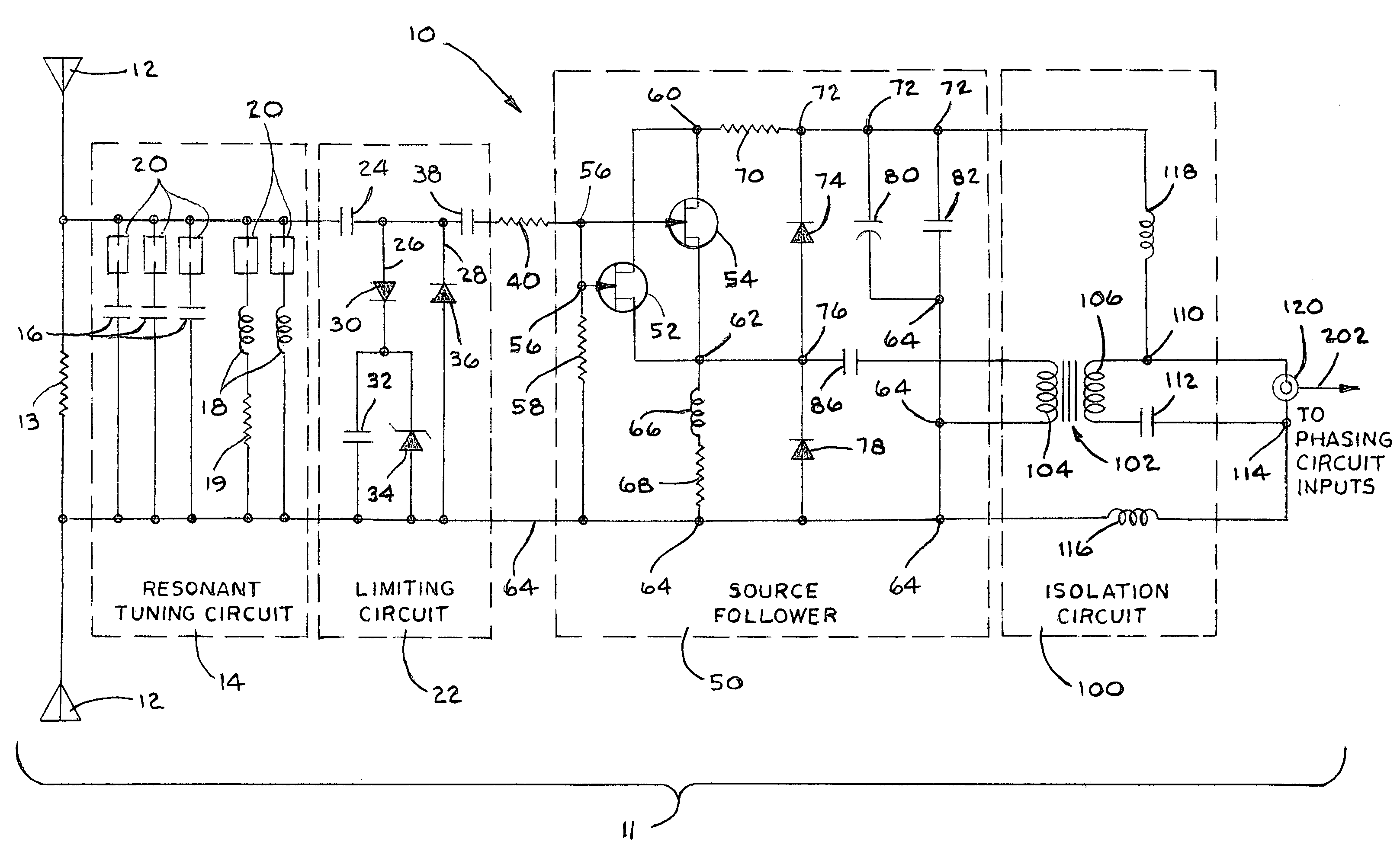
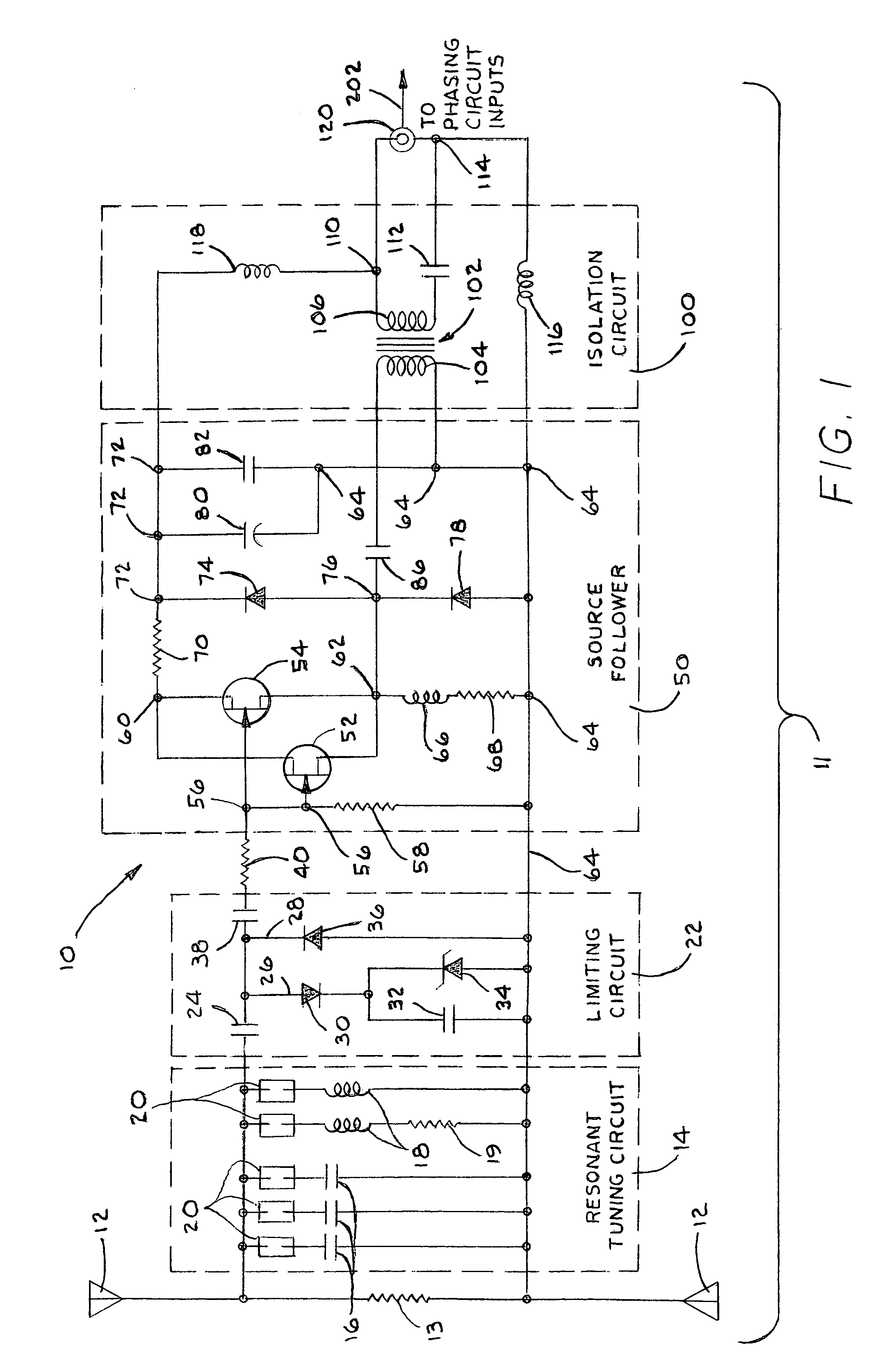
[0022]A phased array antenna system is generally designated by the numeral 10, as shown in the drawings. Antenna system 10 includes an active antenna unit 11, as shown in FIG. 1, which includes a dipole antenna 12 and resistor 13 connected between the dipole feed point terminals. Coupled to the output of dipole antenna 12 is a resonant tuning circuit 14. The resonant tuning circuit 14 contains a plurality of capacitors 16, and a plurality of inductors 18 arranged in parallel. Additionally, a resistor 19 may also be provided in series with one or more of the parallel inductors 18, as shown. The resonant tuning circuit 14 may be user configurable, via one or more jumpers 20, to provide desired tuning to further complement the operating frequency range of the dipole antenna 12. However, it should also be appreciated that the resonant circuit 14 may include a tuning circuit that cannot be adjusted by the user. Coupled to the output of the resonant tuning circuit 14 is a limiting circuit...
PUM
 Abstract
Description
Claims
Application Information