Interfacing hardware emulation to distributed simulation environments

a simulation environment and hardware technology, applied in the field of computer systems, can solve the problems of reducing the value of single-system simulation, affecting the overall simulation throughput of a distributed simulation system, and simulators not being able to simulate the entire model

Active Publication Date: 2008-09-09
ORACLE INT CORP
View PDF46 Cites 35 Cited by
  • Summary
  • Abstract
  • Description
  • Claims
  • Application Information

AI Technical Summary

Benefits of technology

[0009]Each FPGA may include logic under test (representing the portion of the system under test being emulated on the FPGA), a drive logic block, a sample logic block, and a PCI interface. The drive logic block may be configured to drive input signals to the logic under test. The input signals may be driven in response to drive messages generated by a software emulation controller included within the hardware emulation node. The drive messages, in turn, may be generated by the emulation controller in response to simulation information received from other nodes of the system (e.g., a simulation node or other hardware emulation nodes). The sample logic block may be configured to sample an output signal of the logic under test. The sampled output signal may be sent to the emulation controller via the PCI interface, mapped to a logical signal, formatted according to a grammar used by the nodes of the system, and sent to another node (such as a simulation node or other hardware emulation nodes). The sampled output signal may thereby be used to drive simulations and / or emulations at other nodes, while the input signals may be generated in response to simulation events or emulation outputs at other nodes, thereby providing a mechanism for coordinated distributed design verification across the nodes of the system.

Problems solved by technology

However, as the electronic systems (and the components forming systems) have grown larger and more complex, single-system simulation has become less desirable.
In some cases, the simulators may not be capable of simulating the entire model.
Thus, the overall simulation throughput of a distributed simulation system may be limited by the speed of the slowest node in the system.

Method used


Image

  • Interfacing hardware emulation to distributed simulation environments
  • Interfacing hardware emulation to distributed simulation environments
  • Interfacing hardware emulation to distributed simulation environments

Examples


Embodiment Construction

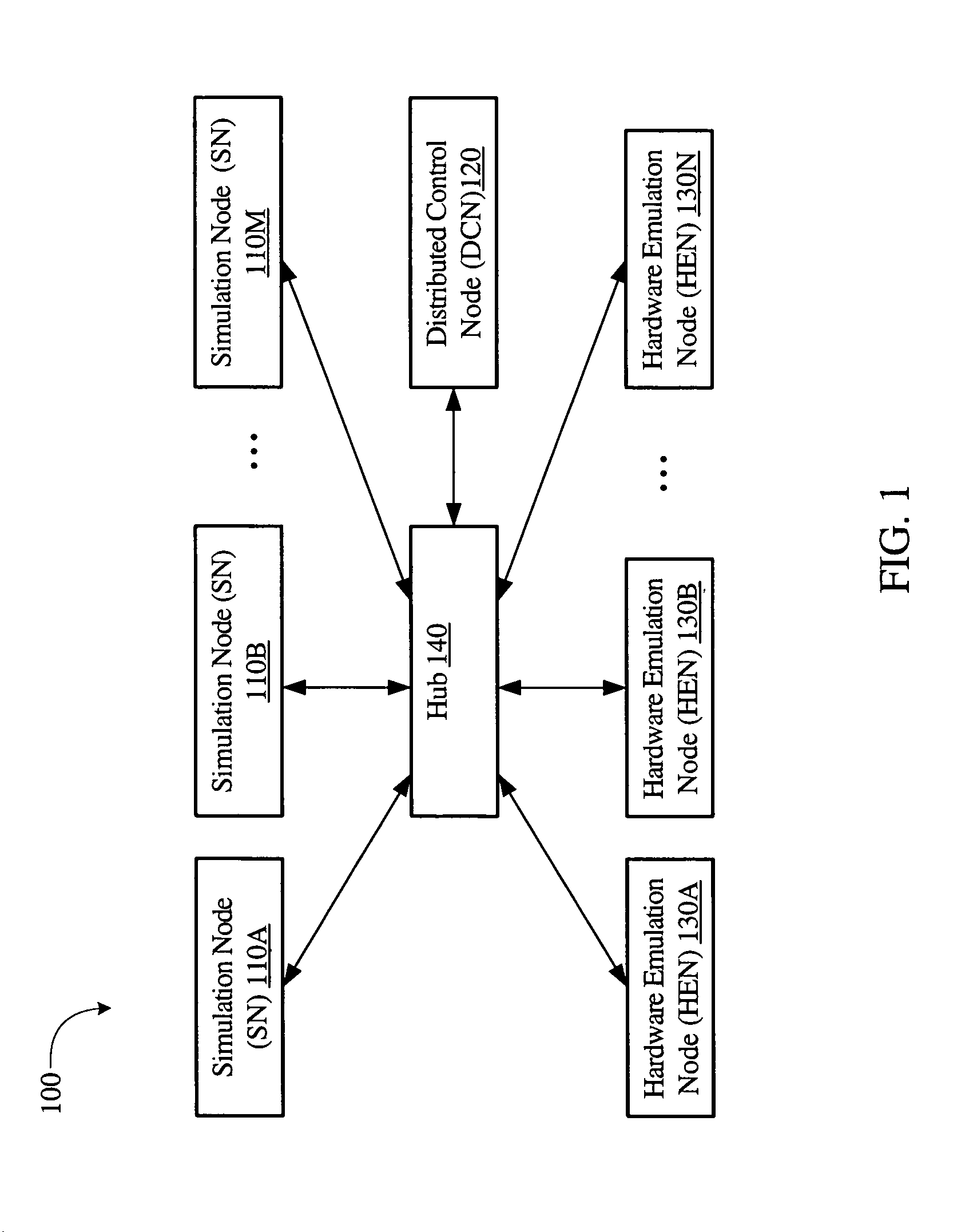
[0020]FIG. 1 is a block diagram of one embodiment of a distributed design verification system 100. In the embodiment of FIG. 1, the distributed design verification system (DDVS) 100 includes a plurality of simulation nodes (SNs) 110A-110M, a plurality of hardware emulation nodes (HENs) 130A-130N, a distributed control node (DCN) 120, and a hub 140. As used herein, a generic element identified to represent a collection of specific elements may be referred to by number alone. For example, a generic SN representative of any of SN 110A-110M may be referred to simply as SN 110.

[0021]Distributed design verification system 100 may be operable to verify the design of an electronic system, such as a computer system, by partitioning the electronic system into a plurality of portions, simulating some portions on SNs 110 and emulating other portions on HENs 130. The electronic system whose design is being verified may be referred to herein as a “system under test”. A system under test represent...


PUM


Abstract

A system for interfacing hardware emulation to software simulation environments may include a simulation node configured to simulate a first portion of a system under test and a hardware emulation node configured to emulate a second portion of the system under test. The hardware emulation node may also be configured to exchange simulation information (such as representations of signal values obtained as output from the emulated portion of the system under test) with the simulation node. The hardware emulation node may contain a field programmable gate array devices (FPGA) configured to perform the hardware emulation. The FPGA may be mounted on an expansion board, such as a PCI (Peripheral Component Interconnect) board.

Description

BACKGROUND OF THE INVENTION[0001]1. Field of the Invention[0002]This invention relates to the field of computer systems and, more particularly, to distributed simulation environments.[0003]2. Description of the Related Art[0004]Generally, the development of components for an electronic system such as a computer system includes design verification of the components, which may be accomplished, for example, by simulation of models of the components. During simulation, the specified functions of each component may be tested and, when incorrect operation (a bug) is detected, the model of the component may be changed to generate correct operation. Once design verification is complete, the model may be fabricated to produce the corresponding component. Since many of the bugs may have been detected in design verification, the component may be more likely to operate as specified and the number of revisions to hardware may be reduced. Simulation models are frequently described in a hardware d...

Claims


Application Information

Patent Timeline
Patent Type & Authority Patents(United States)
IPC IPC(8): G06G7/62G06F13/10G06F17/50G06F9/455
CPCG06F17/5027G06F2217/86G06F30/331G06F2117/08
Inventor CAVANAGH, CARLSIVIER, STEVEN A.
Owner ORACLE INT CORP
Why Eureka
Try Eureka