
Device for dispersing and melting flowable materials

a technology of flowable materials and devices, which is applied in the direction of clay mixing apparatuses, rotary stirring mixers, mixers with horizontally mounted tools, etc., can solve the problems of insufficient agglomerate comminution, high energy consumption, and inability to optimally comminute particles and agglomerates, so as to increase efficiency and repeat the process, the effect of easy fitting

Inactive Publication Date: 2008-09-16
BLACH VERWALTUNGS GMBH
View PDF26 Cites 7 Cited by
  • Summary
  • Abstract
  • Description
  • Claims
  • Application Information

AI Technical Summary

Benefits of technology

"The invention is an apparatus for dispersing and melting flowable substances that has axis-parallel supporting shafts rotatable in the same direction. The apparatus includes screw elements with single or double-flighted screw elements that rotate in the same sense. The screw elements are designed to optimize homogenization and dispersion of the substances being processed. The apparatus also includes a conveying system that allows for elongational flows acting on the substances without increasing temperature or requiring excessive energy consumption. The design of the screw elements with the relatively large effective faces and the short distance between the screw elements results in a more efficient use of space and reduced energy consumption compared to conventional screw extruders. The apparatus can be equipped with only one spline for power transmission and positioning, and the axial length of the screw portions can be adjusted for better power transmission. The invention provides a better solution for dispersing and melting flowable substances compared to conventional methods."

Problems solved by technology

When dispersing solids in a viscous matrix it was hitherto impossible to comminute the particles and agglomerates optimally.
One of the reasons for this is an excessive partial pressure buildup, which leads to high energy consumption with a corresponding temperature increase but produces insufficient agglomerate comminution.

Method used


Image

  • Device for dispersing and melting flowable materials
  • Device for dispersing and melting flowable materials

Examples


Embodiment Construction

)

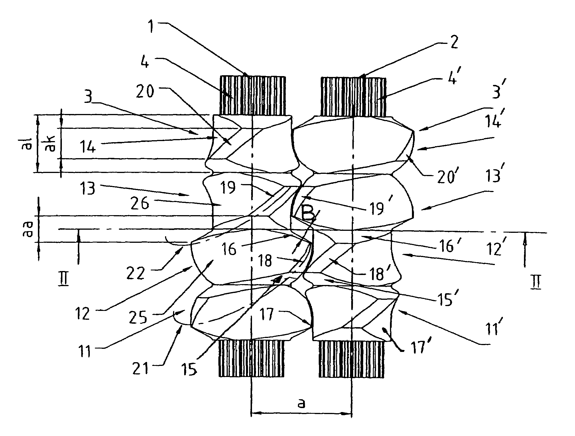
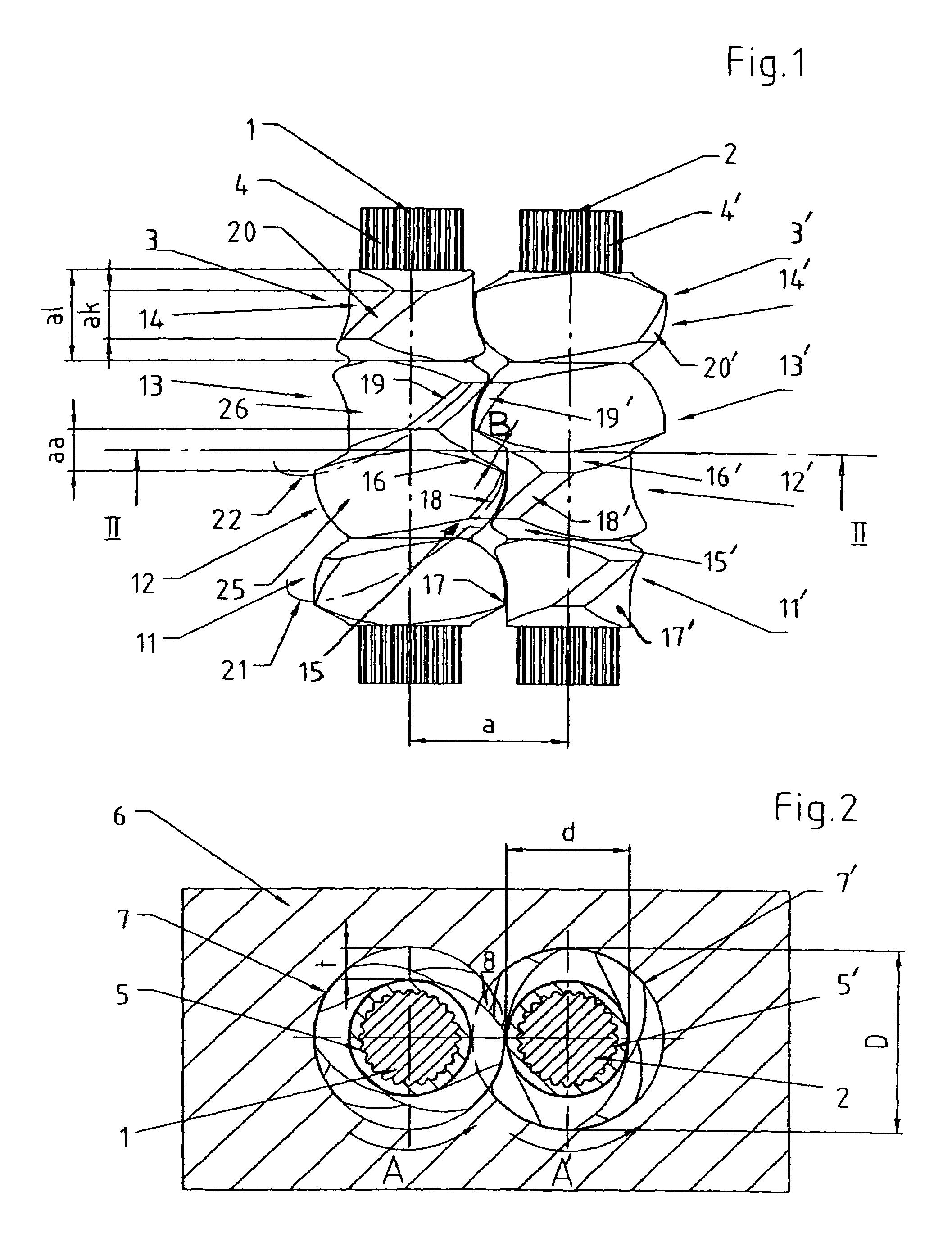
[0035]Accordingly, two axis-parallel supporting shafts 1, 2 are driven by a gear (not shown) in the same direction in accordance with arrows A, A′. Each supporting shaft 1, 2 bears a plurality of screw elements, whereby only one screw element 3, 3′ is shown on each supporting shaft 1, 2.

[0036]For a connection ensuring rotation in unison of screw elements 3, 3′, supporting shafts 1, 2 are provided with a splining with a plurality of ridges or teeth 4, 4′ engaging a corresponding number of longitudinal grooves 5, 5′ in a hollow bore of the core of screw elements 3, 3′ that forms the spline hub. The screw elements are thereby interchangeable on the supporting shafts.

[0037]Housing 6 is provided with two bores 7, 7′ receiving shafts 1, 2 with screw elements 3, 3′. Bores 7, 7′ intersect in cross section so that screw elements 3, 3′ mesh in zone 8.

[0038]Screw elements 3, 3′ are integral, i.e. each consist of only one monolithic part with the hollow bore, having screw portions 11, 12, 13, ...


PUM

PropertyMeasurementUnit
cone angleaaaaaaaaaa
diameteraaaaaaaaaa
angleaaaaaaaaaa

Abstract

An apparatus for dispersing and melting flowable substances includes axis-parallel supporting shafts rotatable in the same direction. Screw elements with the same direction of thread are fitted on the shafts so as to rotate in unison and intermesh. The screw elements have screw portions disposed at a progressive angular offset from each other with the same sense of rotation so as to form faces. The screw elements are of single- or double-flighted form. The axial length of each screw element is a fraction of the pitch of the screw crest of each screw portion.

Description

FIELD OF THE INVENTION[0001]This invention relates to an apparatus for dispersing and melting flowable substances having axis-parallel support shafts rotatable in the same direction. The shafts rotate in unison and are provided with intermeshing screw elements.BACKGROUND OF THE INVENTION[0002]In the apparatus, not only are screw elements fitted on the supporting shafts, but also kneading blocks and similar processing elements for converting an optimum of the driving energy into kneading and mixing power.[0003]To distribute the resin along the screw as evenly as possible during processing, DE 31 34 479 A1 discloses a screw extruder wherein a triple-threaded screw is divided into disks that are fitted on the supporting shaft at a progressive angular offset from each other. The resulting faces on the disks must be provided with central shoulders halfway up so that the relevant faces can move past each other freely upon rotation of the screw.[0004]Due to geometrical relations, the tripl...

Claims


Application Information

Patent Timeline
Patent Type & Authority Patents(United States)
IPC IPC(8): B29B7/48B29C48/03B29C48/395
CPCB29B7/489B29C47/60B29C47/38B29C47/402B29C47/0825B29C47/0009B29C48/03B29C48/2564B29C48/395B29C48/402
Inventor BLACH, JOSEF A.
Owner BLACH VERWALTUNGS GMBH
Learn More