Stagnation point reverse flow combustor

a combustor and reverse flow technology, applied in the field of combustion systems, can solve the problems of large pressure loss in the process, environmental pollution, pollution raising public concerns,

Inactive Publication Date: 2008-09-16
GEORGIA TECH RES CORP
View PDF75 Cites 52 Cited by
  • Summary
  • Abstract
  • Description
  • Claims
  • Application Information

AI Technical Summary

Problems solved by technology

However, with the prevalent occurrences of combustion, one of the major downsides of these processes is environmental pollution.
Such pollutants have raised public concerns.
Also, the system requires high flow velocity of the fuel jets to create the pump action necessary for mixing the fuel with the hot combustion products.
Additionally, since a significant fraction of the large kinetic energy of the injected reactants jets is dissipated within the furnace, the process experiences large pressure losses.
Consequently, in its current design, this process is not suitable for application to land-based gas turbines and aircraft engine's combustors and other processes which require high combustion intensity and / or low pressure losses.

Method used


Image

  • Stagnation point reverse flow combustor
  • Stagnation point reverse flow combustor
  • Stagnation point reverse flow combustor

Examples


Embodiment Construction

[0033]Referring now in more detail to the drawings, the invention will now be described in more detail.

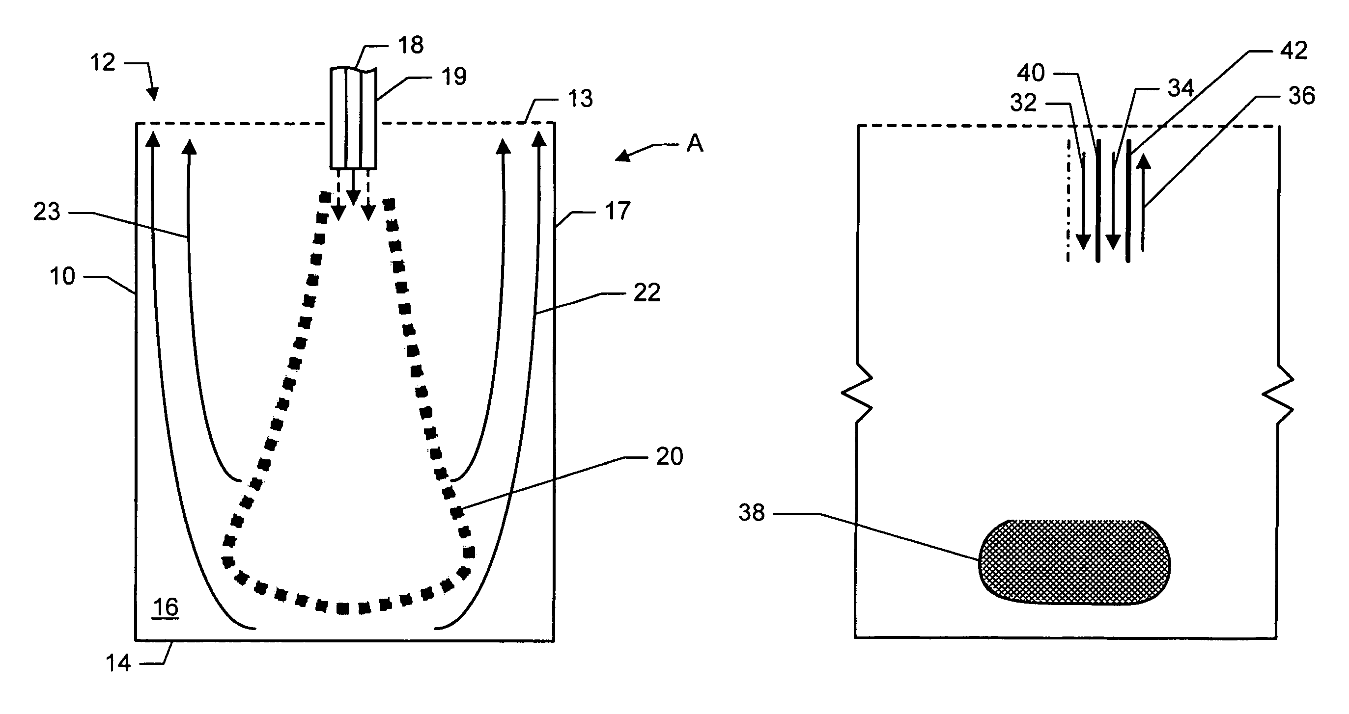
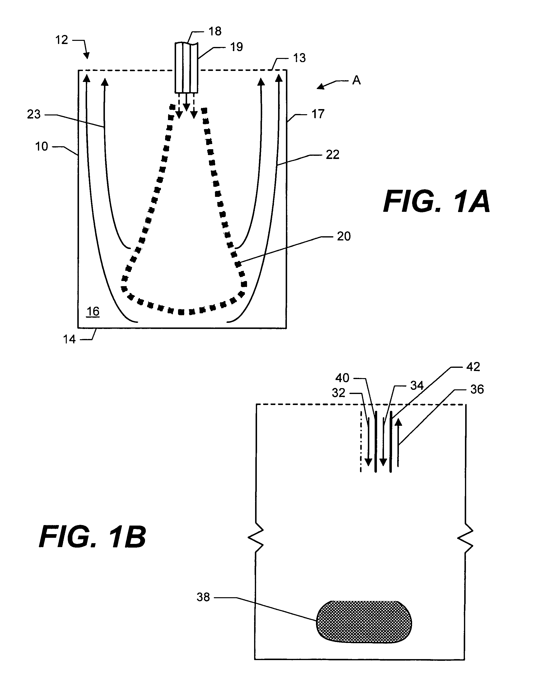
[0034]As shown in FIG. 1A, a system and method of combusting are disclosed. Combustion system A includes a vessel 10 which has a proximate end 12 and a distal closed end 14 defining a combustion chamber 16. Proximate end 12 may define opening 13. Also, opening 13 may be located near proximate end 12 in either sidewall 17. A fuel supply 18 and oxidant supply 19 are provided into the combustion chamber for combustion. An igniter (not shown) ignites the reactants creating a flame 20 and combustion products 22. Due to the geometry of combustion chamber 16, the incoming reactants flow, which initially flows toward the distal closed end, is reversed and the combustion products flow 22 and 23 exit via opening 13.

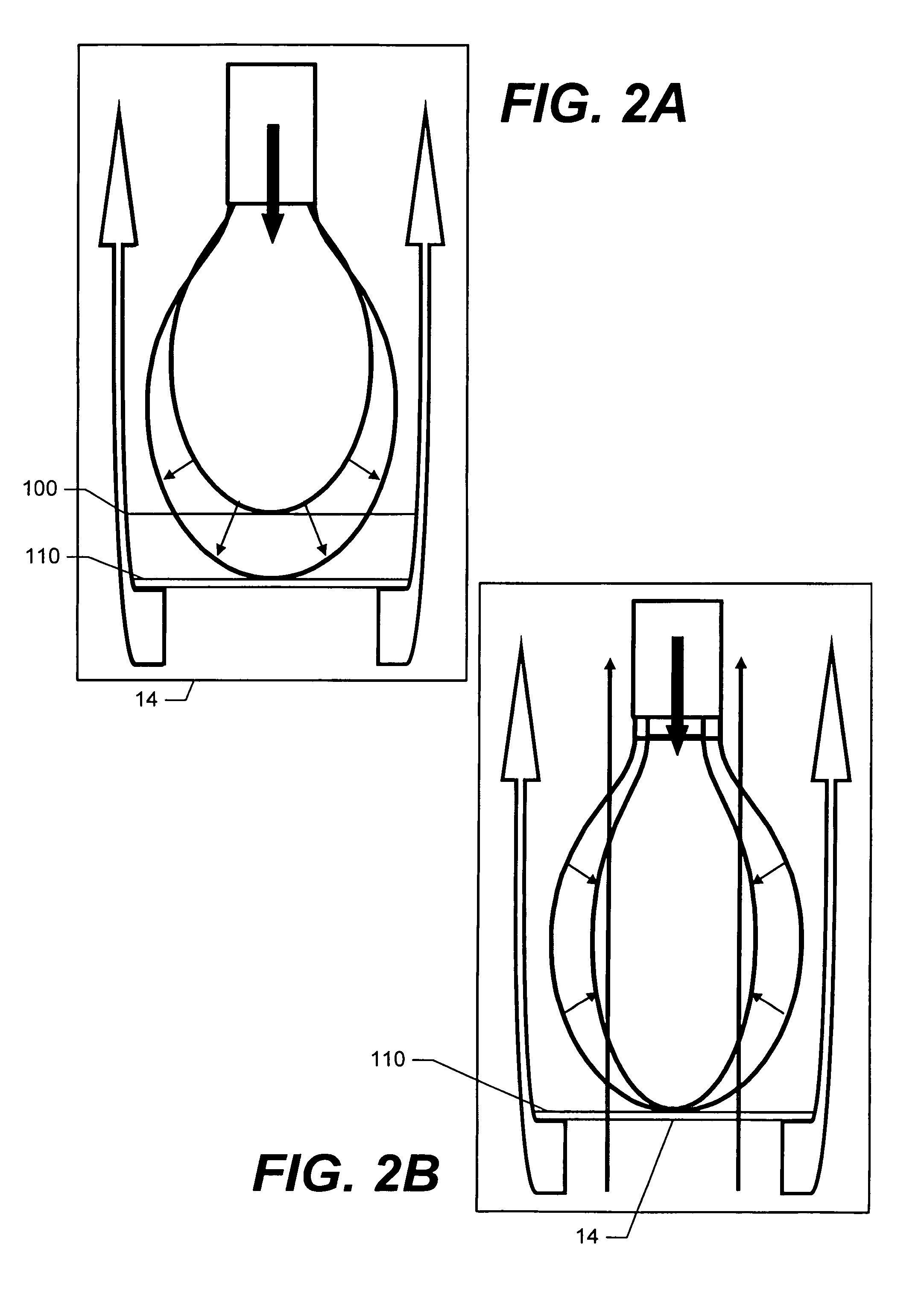
[0035]FIGS. 2A and 2B illustrate the adaptability of the combustion system A. As shown in FIG. 2A, different flame tip locations may be established within the stagnation zone util...


PUM


Abstract

A method for combusting a combustible fuel includes providing a vessel having an opening near a proximate end and a closed distal end defining a combustion chamber. A combustible reactants mixture is presented into the combustion chamber. The combustible reactants mixture is ignited creating a flame and combustion products. The closed end of the combustion chamber is utilized for directing combustion products toward the opening of the combustion chamber creating a reverse flow of combustion products within the combustion chamber. The reverse flow of combustion products is intermixed with combustible reactants mixture to maintain the flame.

Description

BENEFIT CLAIMS TO PRIOR APPLICATIONS[0001]This application claims the benefit of U.S. Provisional Application No. 60 / 578,554 filed on Jun. 10, 2004.GOVERNMENT INTERESTS[0002]This invention was made in part during work supported by the U.S. Government, including grants from the National Aeronautics and Space Administration (NASA), #NCC3-982. The government may have certain rights in the invention.FIELD OF THE INVENTION[0003]This invention relates to combustion systems in general and more particularly to a combustion system which utilizes a combustion chamber design for low pollutant emissions by creating a stagnation point for anchoring a flame and reverse flow of combustion products that partially mixes with the incoming reactants.BACKGROUND[0004]Combustion and its control are essential features to everyday life. Approximately eighty-five percent of the energy used in the United States alone is derived via combustion processes. Combustion of combustible resources is utilized for, am...

Claims


Application Information

Patent Timeline
Patent Type & Authority Patents(United States)
IPC IPC(8): F23M3/00F23C5/24F23C9/00F23L1/00F23R3/42F23R3/54
CPCF23C5/24F23C9/006F23R3/54F23R3/42F23C2900/03006
Inventor ZINN, BEN T.NEUMEIER, YEDIDIASEITZMAN, JERRY M.JAGODA, JECHIELWEKSLER, YOAV
Owner GEORGIA TECH RES CORP
Why Eureka
Try Eureka