Method and apparatus for selectively providing data from a test head to a processor

a technology of data transmission and data transmission, applied in the direction of optically investigating flaws/contamination, instruments, material analysis, etc., can solve the problem of large amount of data generated by the detector

Inactive Publication Date: 2008-09-16
WESTERN DIGITAL TECH INC
View PDF38 Cites 74 Cited by
  • Summary
  • Abstract
  • Description
  • Claims
  • Application Information

AI Technical Summary

Problems solved by technology

Typically, the detectors generate a large amount of data.

Method used


Image

  • Method and apparatus for selectively providing data from a test head to a processor
  • Method and apparatus for selectively providing data from a test head to a processor
  • Method and apparatus for selectively providing data from a test head to a processor

Examples


Embodiment Construction

I. Overview of Optical Inspection Apparatus 10

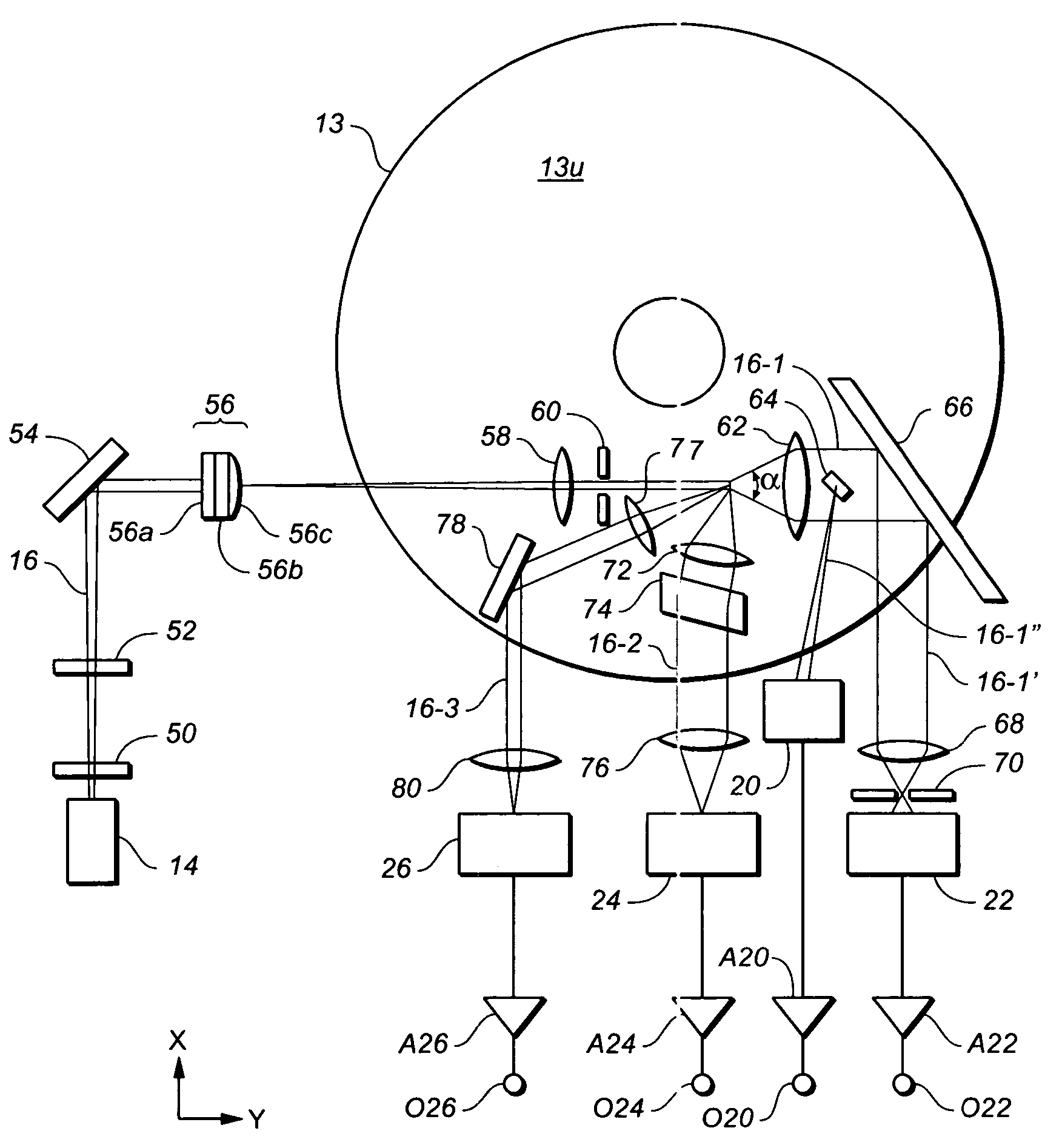
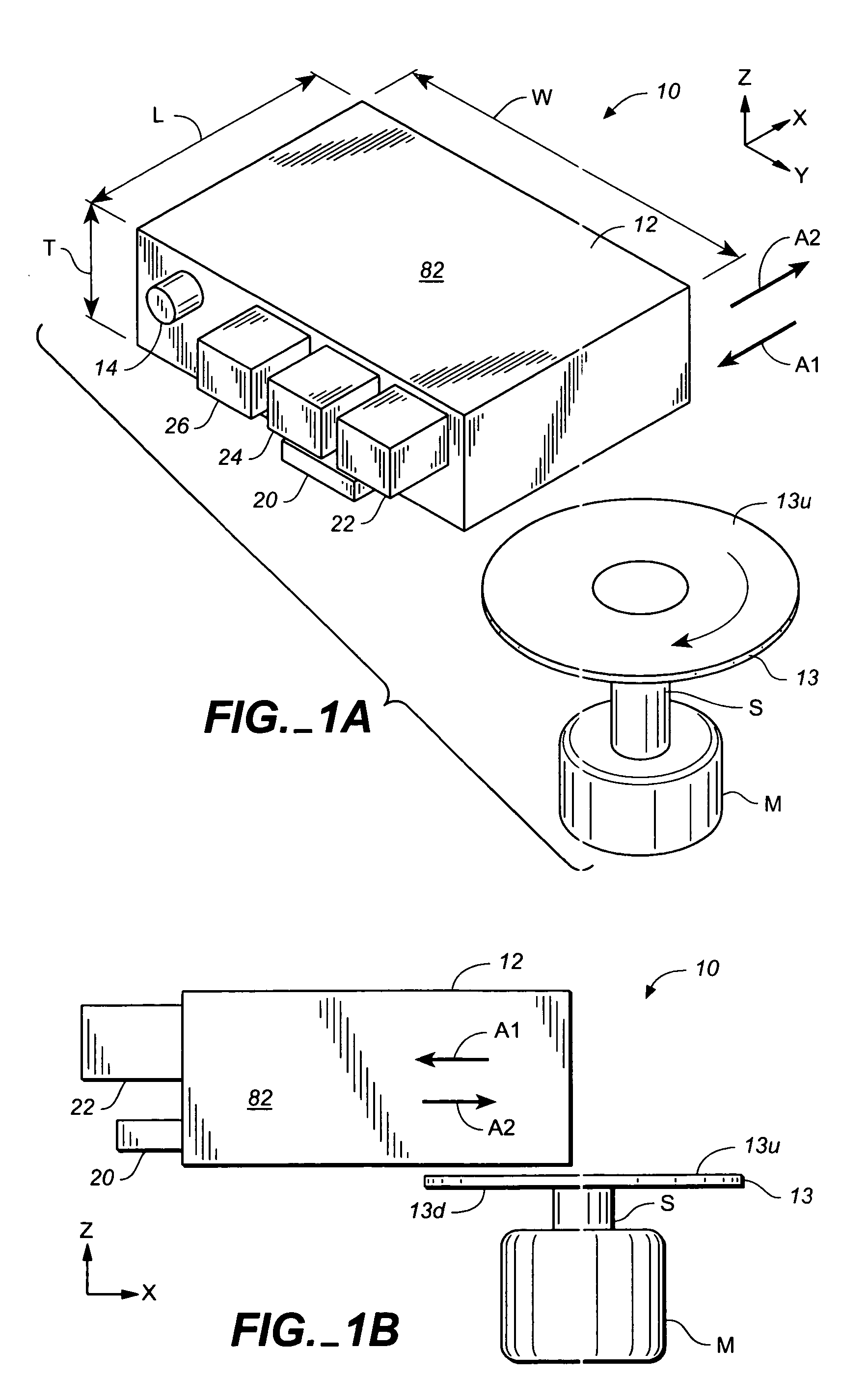
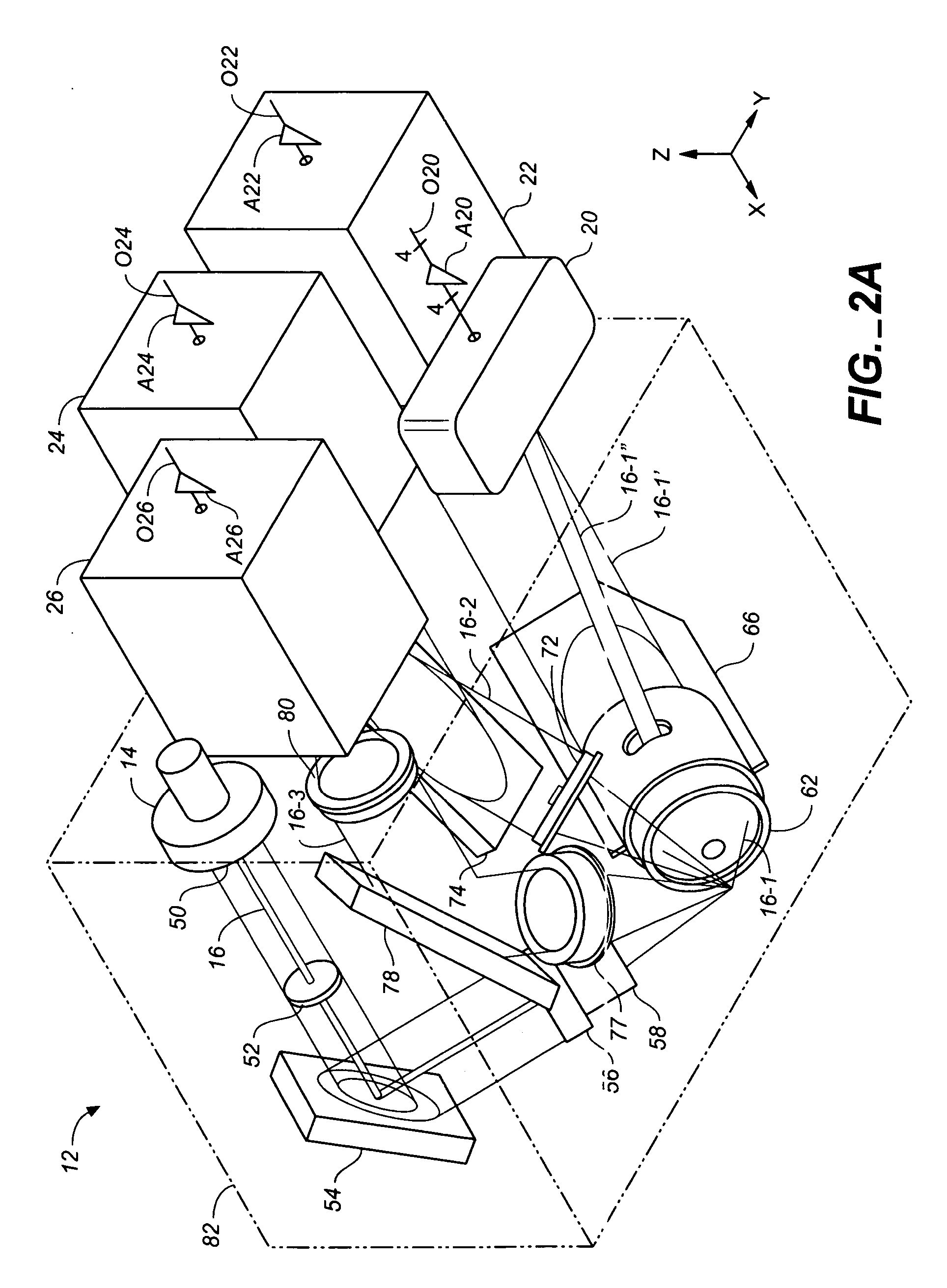
[0036]FIGS. 1A, 1B, 2A and 2B schematically illustrate an example of an optical inspection apparatus 10 in accordance with the invention that includes a head 12 for optically inspecting a top surface 13u of a workpiece 13 (typically a platter). (FIGS. 1A and 1B show the exterior of head 12 in schematic form. The actual appearance of head 12, in one embodiment, is shown in FIGS. 3A to 3D. FIGS. 2A and 2B show the optical paths and elements within head 12.) Head 12 comprises a laser source 14 for providing a laser beam 16. Head 12 also includes a) a set of lenses, masks, mirrors and other optical elements (described below) for modifying laser beam 16 and directing and focusing beam 16 onto a spot on surface 13u; and b) a set of mirrors, lenses and other optical elements (also described below) for modifying and directing light reflected by surface 13u to various detectors 20-26 (discussed below). (As used herein, “reflected” includes specul...


PUM

PropertyMeasurementUnit
angleaaaaaaaaaa
angleaaaaaaaaaa
angle of incidenceaaaaaaaaaa

Abstract

An optical test head comprises one or more detectors for providing output signals indicative of the condition of a workpiece surface. Data from these detectors are stored in one or more memories only when the data from the detectors satisfy one or more conditions (e.g. the data exceed than a particular threshold). The data are then passed from the one or more memories to an electrical circuit for processing. In addition, location information is stored in one or more memories and passed on to the electrical circuit when the data from the detectors satisfy the one or more conditions.

Description

CROSS-REFERENCE TO PROVISIONAL PATENT APPLICATION[0001]This application claims priority based on U.S. provisional patent application No. 60 / 643,748, filed Jan. 13, 2005.BACKGROUND OF THE INVENTION[0002]This invention relates to methods and apparatus for communicating data from data collecting apparatus to a memory and / or an electronic circuit such as a processor.[0003]Magnetic disks are typically manufactured using the following method.[0004]1. A disk-shaped substrate (typically an Al alloy) is lapped or ground.[0005]2. A material such as a nickel phosphorus alloy is plated onto the substrate.[0006]3. The plated substrate is polished and textured. (During texturing, texture grooves are typically formed in the substrate by mechanical abrasion to cause a subsequently deposited magnetic layer to exhibit anisotropy. It is also known to laser texture substrates for tribological reasons)[0007]4. One or more underlayers, one or more magnetic layers and one or more protective overcoats are ...

Claims


Application Information

Patent Timeline
Patent Type & Authority Patents(United States)
IPC IPC(8): G01N21/86G01N21/00G01V8/00
CPCG01N21/8851
Inventor TREVES, DAVIDO'DELL, THOMAS A.
Owner WESTERN DIGITAL TECH INC
Why Eureka
Try Eureka