Magnetoresistive sensor

a magnetoresistive sensor and sensor technology, applied in the field of magnetoresistive sensors, can solve the problems of not being reliable or efficient in detecting tooth edges

Active Publication Date: 2008-09-16
SENSATA TECHNOLOGIES INC
View PDF30 Cites 12 Cited by
  • Summary
  • Abstract
  • Description
  • Claims
  • Application Information

AI Technical Summary

Problems solved by technology

One of the problems with magnetic detection devices, such as the sensors described above, is that such devices, while adequate for tooth and slot detection, are not very reliable or efficient in detecting a tooth edge.

Method used


Image

  • Magnetoresistive sensor
  • Magnetoresistive sensor
  • Magnetoresistive sensor

Examples


Embodiment Construction

[0033]The particular values and configurations discussed in these non-limiting examples can be varied and are cited merely to illustrate at least one embodiment and are not intended to limit the scope thereof.

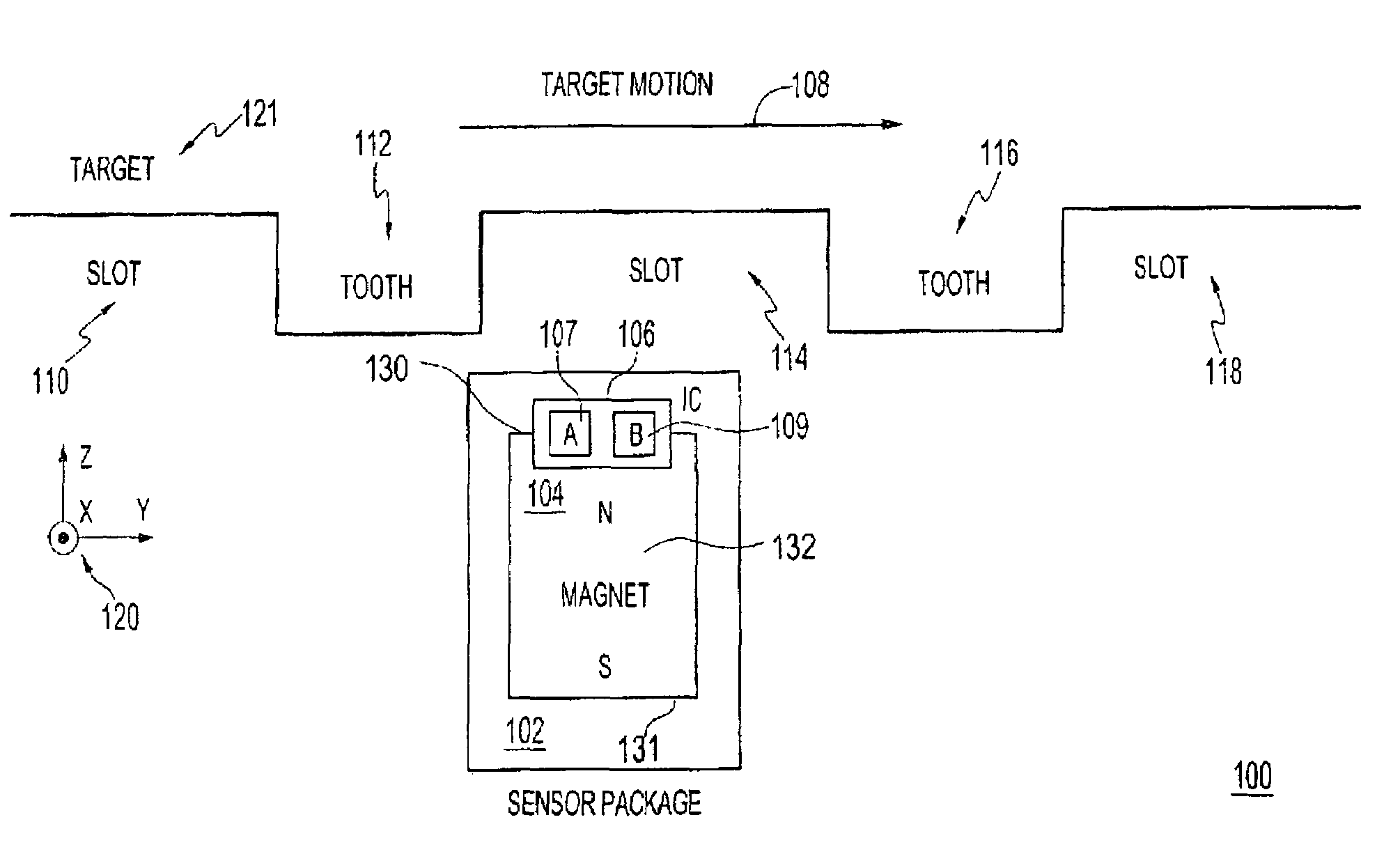
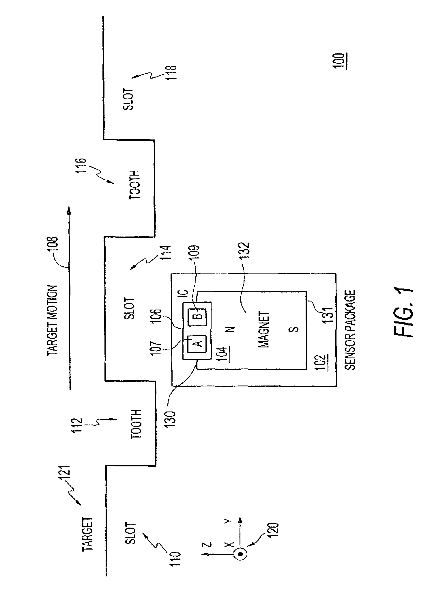
[0034]FIG. 1 illustrates a block diagram of an X-axis view of a magnetoresistive sensing system 100 including a sensor package and a target being sensed, in accordance with a preferred embodiment. Note that in FIGS. 1-5 herein, identical or similar parts or elements are generally indicated by identical reference numerals. System 100 generally includes a magnet 104 located proximate to a target 121 having a plurality of teeth 112, 116 and a plurality of slots 110, 114, 118 thereof. Slot 112 is formed to the left of tooth 112 while slot 114 is configured between tooth 112 and 116. Slot 118 is located to the right of tooth 116. Although only a few teeth 112, 116 and a few slots 110, 114, 118 are depicted in the configuration of system 100, it can be appreciated that target 121 can...


PUM


Abstract

A magnetic sensor, system and method include a magnet located proximate to a target comprising a plurality of teeth and a plurality of slots formed therebetween. An integrated circuit is located on a side of the magnet wherein the integrated circuit comprises a plurality of magnetoresistive bridge components. The integrated circuit and the magnet are configured into a sensor package, such that the magnetoresistive bridge components enable the detection of a target tooth when one half of the plurality of magnetoresistive bridge components come into proximity with an edge of a tooth before that of another half of the magnetoresistive bridge components as the tooth and an associated slot thereof pass by the sensor package.

Description

CROSS-REFERENCE TO PROVISIONAL PATENT APPLICATION[0001]This patent application claims priority under 35 U.S.C. § 119(e) to provisional patent application Ser. No. 60 / 683,628 entitled “Magnetoresistive Sensor,” which was filed on May 20, 2005, the disclosure of which is incorporated herein by reference.TECHNICAL FIELD[0002]Embodiments are generally related to magnetoresistive sensors. Embodiments are also related to geartooth, crankshaft and camshaft sensors. Embodiments additionally relate to speed and transmission sensors. Embodiments additionally relate to Chip-On-Lead-Frame (COLF) construction techniques and packaging components thereof.BACKGROUND OF THE INVENTION[0003]Many different types of sensors are known to those skilled in the art. Some sensors utilize permanent magnets to detect the presence or absence of a magnetically permeable object within a certain predefined detection zone relative to the sensor. In combination with the permanent magnet, some sensors of this type ut...

Claims


Application Information

Patent Timeline
Patent Type & Authority Patents(United States)
IPC IPC(8): G01B7/30G01R33/05G01R33/09
CPCG01D5/145G01D11/245G01D5/147G01D2205/771G01R33/038
Inventor BUSCH, NICHOLAS F.
Owner SENSATA TECHNOLOGIES INC
Why Eureka
Try Eureka