Series motor and method of controlling the same

a series motor and motor technology, applied in the direction of dynamo-electric machines, ac motor stoppers, dc motor stoppers, etc., can solve the problems of insufficient reliability, failure of semiconductors, and failure of power tools, so as to avoid the risk of motor briefly starting up

Inactive Publication Date: 2008-09-23
C & E FEIN GMBH & CO KG
View PDF15 Cites 20 Cited by
  • Summary
  • Abstract
  • Description
  • Claims
  • Application Information

AI Technical Summary

Benefits of technology

[0010]It is a forth object of the invention to disclose a power tool allowing a safe testing of the controls thereof before switching on its motor.
[0049]In this way, by connecting the protective switch in parallel, it is possible to test for any malfunction in the driver circuit for the protective switch prior to switching on the control switch, and for deactivation to be effected should the control switch fail.

Problems solved by technology

Although electronics are becoming more and more widespread in power tools as well, controlling power tools solely by means of power semiconductors that also serve to switch the power tool on and off is considered to be insufficiently reliable.
The reason for this is that semiconductors can break down (internal short circuit) and then can no longer be controlled.
However, circuits of this kind operate reliably only when erratic behavior on the part of the machine and the electronic switching element is detected and the appliance can be brought to a defined OFF state, and any defect in the protection circuit can also be detected in order to put the appliance into a defined OFF state.

Method used


Image

  • Series motor and method of controlling the same
  • Series motor and method of controlling the same
  • Series motor and method of controlling the same

Examples


Embodiment Construction

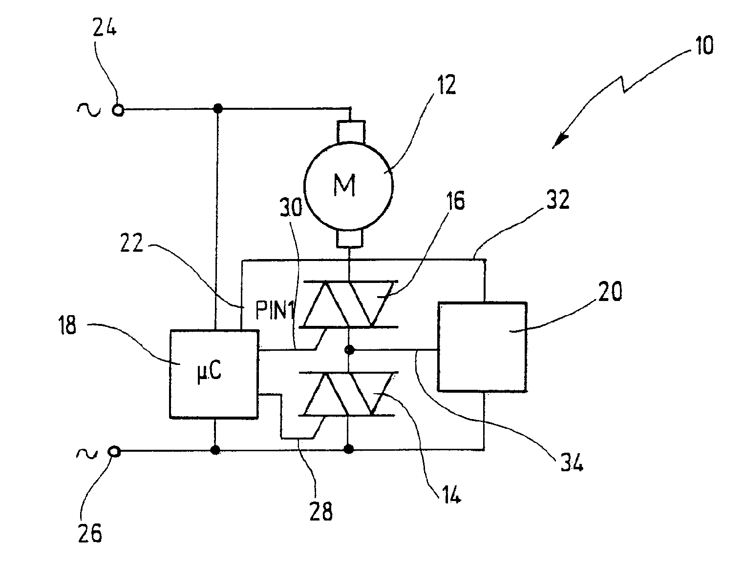
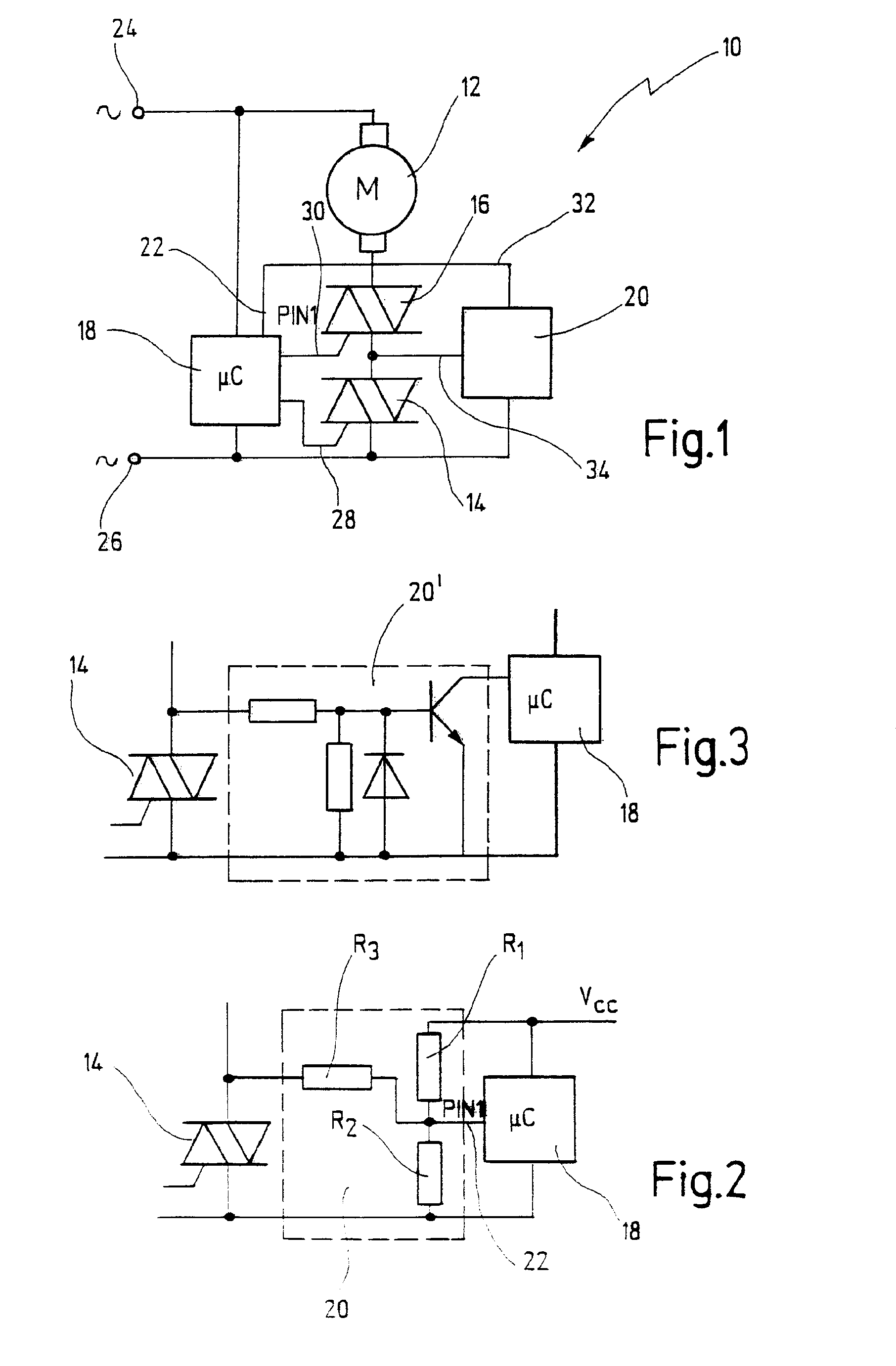
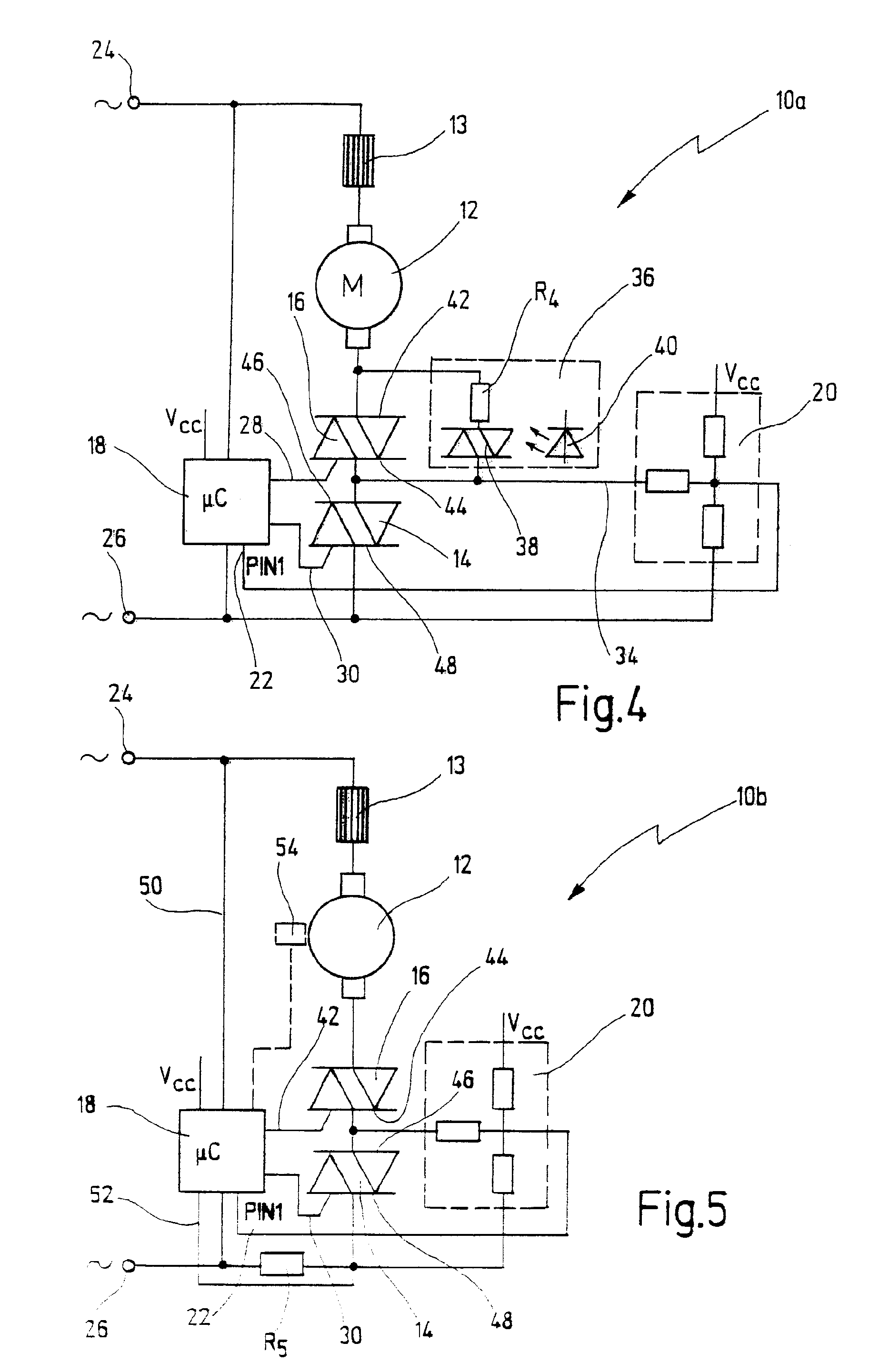
[0059]FIG. 1 shows an electric motor according to the invention, in the form of a series motor circuit and labeled in its entirety with reference numeral 10.

[0060]The motor 10 is supplied with 230 V from the two poles 24 and 26 of an alternating voltage source. Motor 10 has an armature 12, the field windings of which (not shown) are wound in series and connected to the one pole 24 of the supply voltage. The other pole of the armature 12 is connected to the other pole 26 of the supply voltage via two triacs in series, namely a protective switch 16 and a control switch 14. Control terminals 28 and 30 of control switch 14 and protective switch 16 are connected to the terminals of an electronic controller 18 in the form of a microprocessor. Electronic controller 18 is likewise connected to the two poles 24 and 26 of the supply voltage source, and is supplied in addition with a DC supply (unless this voltage supply is not already integrated in electronic controller 18). A monitoring circ...


PUM


Abstract

A circuit for a series motor for a power tool is disclosed, wherein reliable switching is achieved by means of two electronic switches, without the use of a mechanically disconnecting switch. To this end, two electronic switches, preferably triacs, are preferably connected in series to each other, the voltage drop across the triacs being continuously monitored by a monitoring circuit. A check for faults can be carried out before switching on the power tool. Alternatively, a fusible cutout can be tripped by means of a protective switch connected in parallel thereto.

Description

CROSSREFERENCES TO RELATED APPLICATIONS[0001]This application is a continuation of International Patent Application PCT / EP2005 / 003237, filed on Mar. 26, 2005 designating the U.S., which International Patent Application has been published in German language and claims priority of German patent application 10 2004 018 966.8, filed on Apr. 13, 2004 the entire contents of which is incorporated herein by reference.BACKGROUND OF THE INVENTION[0002]The invention relates to a series motor comprising contactless switching elements for interrupting operation, said elements being embodied in the form of electronic switches.[0003]Power tools are generally driven by electric motors that are configured as series motors (universal motors) and controlled by means of mechanical switches. Although electronics are becoming more and more widespread in power tools as well, controlling power tools solely by means of power semiconductors that also serve to switch the power tool on and off is considered to...

Claims


Application Information

Patent Timeline
Patent Type & Authority Patents(United States)
IPC IPC(8): H02P7/00H02H3/02H02H3/04H02H7/08H02P25/14
CPCH02H7/0844H02H3/023Y10S388/937H02H3/044H02H7/08
Inventor KRESS, CHRISTOFBEICHTER, MARTIN
Owner C & E FEIN GMBH & CO KG
Why Eureka
Try Eureka